3 - 61 3 - 61
MELSEC-Q
3 SPECIFICATIONS
3.4.14 Input signal error detection flag (buffer memory address 49: Un\G49)
(1) If the analog input value detected falls outside the setting range sets to the CH
input signal error detection setting value/CH
input signal error detection lower
limit setting value (buffer memory addresses 138 to 141: Un\G138 to Un\G141),
or CH
input signal error detection upper limit setting value (buffer memory
addresses 142 to 145: Un\G142 to Un\G145), the Input signal error detection flag
for the corresponding channel turns to 1.
(2) By bringing the analog input value within the setting range and then turning ON
the Error clear request (YF), the Input signal error detection flag turns OFF.
(3) If the warning is detected on any one of the channels enabled for input signal
error detection and enabled for A/D conversion, the Input signal error detection
signal (XC) also turns ON.
(4) When the operating condition setting request (Y9) is turned ON, the Input signal
error detection flag is cleared.
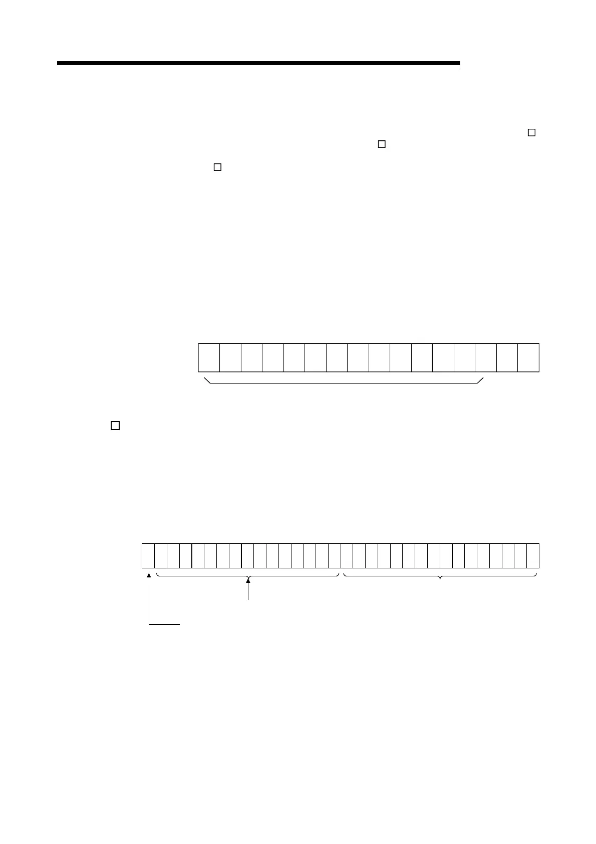
b15 b14 b13 b12 b11 b10 b9 b8 b7 b6 b5 b4 b3 b2 b1 b0
CH4 CH3 CH2 CH1
000000000000
For Q64AD-GH, information of b4 to b15 is fixed at 0.
For Q62AD-DGH, information of b2 to b15 is fixed at 0.
0: Normal
1: Input signal error
3.4.15 CH digital output value (32bit) (buffer memory addresses 54 to 61: Un\G54 to
Un\G61)
(1) The digital output values converted from analog to digital are stored into the
buffer memory addresses 54 to 61 (Un\G54 to Un\G61) channel by channel.
(2) The digital output value is represented in 32-bit signed binary. (The data part is
16 bits long.)
b31 b24 b23 b16 b15 b8 b7 b0
Signed bit
1: Negative
0: Positive
Data section
Bits other than data section and signed bit are 1 when value
is negative (1 in b31) or 0 when value is positive (0 in b31).
(3) While Operating condition setting request is ON, 0 is stored in this area.
(4) For the read-out of digital output values, configure A/D conversion completed
flag (XE) or A/D conversion completed flag (buffer memory address 10: Un\G10)
to act as an interlock.
 Loading...

