8
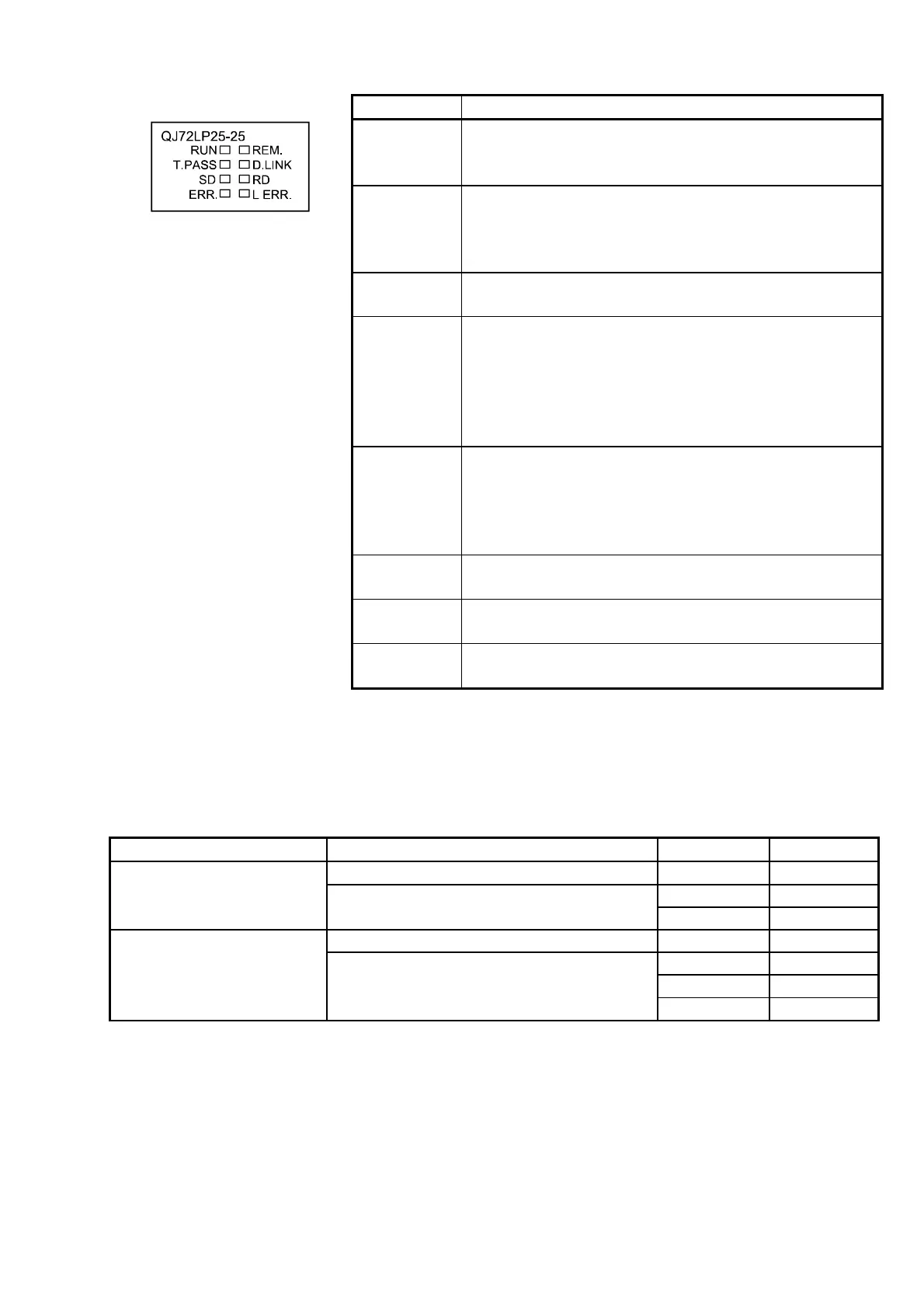
(1) LED displays
LED name Description
RUN On: Module operating normally
Off: Watchdog timer error occurred (hardware
error)
T. PASS On: Executing baton pass
Flashing: Executing test
Off: Baton pass not yet executed
(host is disconnecting)
SD On: Data being sent
Off: Data not yet sent
ERR. *2 On: Setting error occurred
Flashing:
• Error detected by a test
• The mode setting switch or the station number
setting switch was changed during operation *1
Off: No setting error
REM. *2 On: Module operating normally
Flicker: Parameters being written to flash ROM
or device is in test mode.
Off: In remote initialization, watchdog timer error,
Fuse break off, Unit verify error occurred
D. LINK On: Data link being executed
Off: Data link not yet executed
RD On: Data being received
Off: Data not yet received
L ERR. On: A communication error occurred
Off: No communication error
*1: The ERR. LED flashes on the QJ72LP25-25 and QJ72BR15 whose first five digits of the
serial number is “02112” or later.
*2: When a remote I/O module is used in a redundant power supply system, the REM. LED
and ERR. LED indicate errors as follows according to the failure causes of the power
supply module.
Power supply module Failure cause REM. LED ERR. LED
Input power supply off, fuse blown Off On
Off On
Failure of only one
module
Internal failure
On Off
Input power supply off, fuse blown Off Off
Off Off
Off On
Failure of both the two
modules
Internal failure (Both the LEDs are off
or on depending on the failure part.)
On Off
When a remote I/O module of function version C or later is used, the ERR.
LED remains off even if one or two power supply modules fail.
Confirm the failure of the power supply module on the LED of the module. If
the power supply module is mounted on an extension base unit, the error
can also be confirmed by the ERR contact of the power supply module. (For
the specification of the LED of the power supply module, refer to QCPU
User's Manual (Hardware Design, Maintenance and Inspection).)

 Loading...


