7
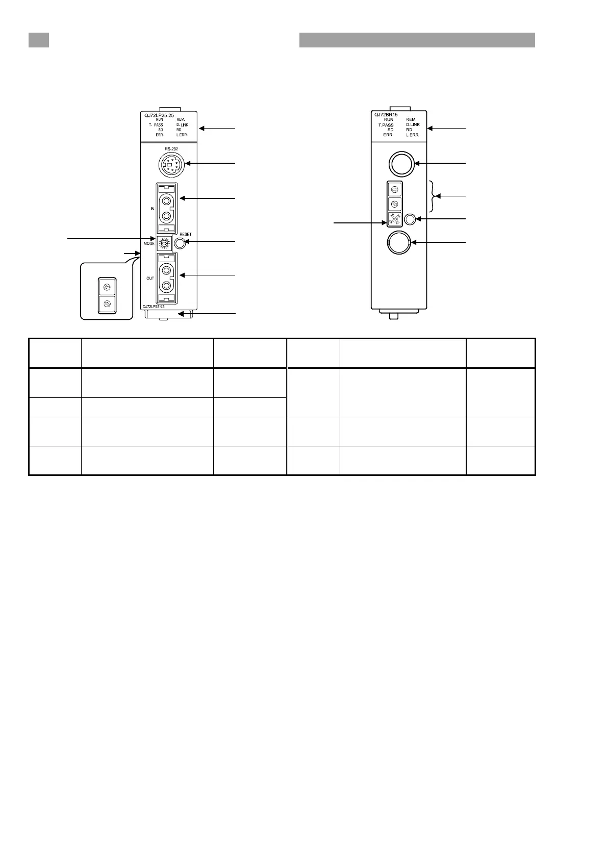
4. Part Identification Names
QJ72LP25-25, QJ72LP25G QJ72BR15
0
5
9
4
8
3
7
2
6
1
0
5
9
4
8
3
7
2
6
1
STATION NO.
X10
X1
QJ72BR15
0
8
D
5
C
4
9
1
0
5
9
4
8
3
7
2
6
1
0
5
9
4
8
3
7
2
6
1
MODE
STATION
X10
X1
NO.
RESET
RS-232
1)
2)
6)
5)
6)
4)
3) (Left side)
1)
2)
3)
6)
5)
4)
7)
Number Name
Reference
Section
Number Name
Reference
Section
1) LED indicator section
(1) in this
chapter
2) RS-232 connector ----
5) RESET switch *1 ----
3)
Station number setting
switches
(2)(a) in this
chapter
6) Coaxial connector
(3) in this
chapter
4) Mode setting switch
(2)(b) in this
chapter
7) Serial number plate *2 ----
*1: When resetting the system, press and hold the RESET switch for a second or
more. If the pressing time is too short, the system may not be reset normally.
If the system is not reset normally, try reset operation again.
*2: Indicates the serial No. of the network module. (QJ72LP25-25 only)

 Loading...


