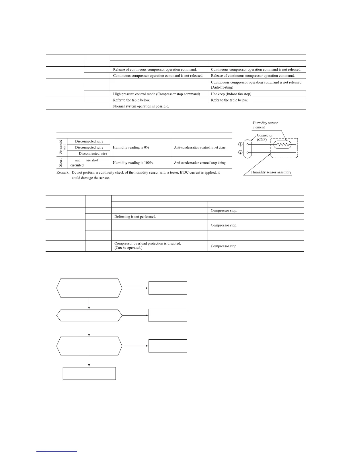
(8) Phenomenon observed after shortcircuit, wire breakage on sensor
(a) Indoor unit
Sensor
Operation
mode
Phenomenon
Shortcircuit Disconnected wire
Room temperature
sensor
Cooling
Heating
Heat exchanger
sensor
Cooling
Heating
Humidity sensor
Cooling
Heating
■
Humidity sensor operation
Failure mode Control input circuit resding
Air conditioning system operation
①
②
①②
① ②
Freezing cycle system protection trips and stops the compressor.
circuit
'09•SRK-DB-087D
(9) Checking the indoor electrical equipment
(a) Indoor PCB check procedure
(b) Outdoor unit
Is there voltage between terminal
blocks
①
and
②
? (AC 220/230/240
V)
Indoor electrical components
are normal.
Is the voltage between terminal
blocks
②
and
③
oscillating between
DC 0 and 20V?
Inspect power source
for outdoor unit.
Replace fuse.
Replace indoor PCB.
Is the fuse burnt out? (3.15 A)
YES
YES
YES
NO
NO
NO
(b) Indoor unit fan motor check procedure
1) Indoor PCB output check
① ④ ⑤
2) Fan motor resistance check
⑥ ⑤ ④ ③ ② ①
⑥ ⑤ ④ ③ ② ①
FM
I
DC15V
Indoor PCB
DC 308~336V
DC several V
(4~6 V)
CNU
(–)
GND
Blue
Yellow
White
Black
Red
Sensor
Operation
mode
Phenomenon
Shortcircuit Disconnected wire
Heat exchanger
sensor
Cooling
Heating
Ourdoor air
temperature sensor
Cooling
Heating
Discharge pipe
sensor
All modes
Measuring point Resistance when normal
①
−
③
−
④
−
③
−
Measuring
point
Resistance when
normal
①
−
③
④
−
③
⑤
−
③
⑥
−
③
Defrosting is performed for 10 minutes at approx. 35 minutes.
Defrosting is performed for 10 minutes at approx. 35 minutes.
k
M
Compressor stop.
The compressor cannot pick up its speed owing to the current
safe so that the designed capacity is not achieved.
The compressor cannot pick up its speed owing to the heating
overload protection so that the designed capacity is not achieved.
'09•SRK-DB-087D
(9) Checking the indoor electrical equipment
(a) Indoor PCB check procedure
(b) Outdoor unit
Is there voltage between terminal
blocks
①
and
②
? (AC 220/230/240
V)
Indoor electrical components
are normal.
Is the voltage between terminal
blocks
②
and
③
oscillating between
DC 0 and 20V?
Inspect power source
for outdoor unit.
Replace fuse.
Replace indoor PCB.
Is the fuse burnt out? (3.15 A)
NO
YES
YES
NO
YES
NO
(b) Indoor unit fan motor check procedure
1) Indoor PCB output check
① ④ ⑤
2) Fan motor resistance check
⑥ ⑤ ④ ③ ② ①
⑥ ⑤ ④ ③ ② ①
FM
I
DC15V
Indoor PCB
DC 308~336V
DC several V
(4~6 V)
CNU
(–)
GND
Blue
Yellow
White
Black
Red
Sensor
Operation
mode
Phenomenon
Shortcircuit Disconnected wire
Heat exchanger
sensor
Cooling
Heating
Ourdoor air
temperature sensor
Cooling
Heating
Discharge pipe
sensor
All modes
Measuring point Resistance when normal
①
−
③
−
④
−
③
−
Measuring
point
Voltage range when
normal
①
−
③
④
−
③
⑤
−
③
Defrosting is performed for 10 minutes at approx. 35 minutes.
Defrosting is performed for 10 minutes at approx. 35 minutes.
k
M
 Loading...