L2
L3
L4
L1
300
100
250
Open
Ⅰ Ⅱ
Open
250
100
500
Ⅲ
Open
250
150
250
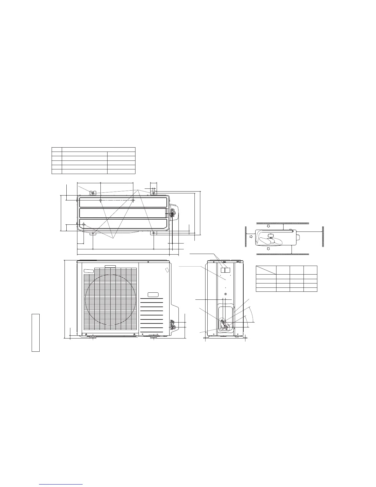
Examples of
Dimensions
installation
L1
L3
Intake
L2
Intake
Outlet
Note
(1)It must not be surrounded by walls on four sides.
(2)The unit must be fixed with anchor bolts. An anchor bolt
must not protrude more than 15mm.
(3)Where the unit is subjected to strong winds, lay it in such a
direction that the blower outlet faces perpendicularly to the
dominant wind direction.
(4)Leave 1m or more space above the unit.
(5)A wall in front of the blower outlet must not exceed the
unit's height.
(6)The model name label is attached on the rear panel.
Minimum installation space
D
C
E
Symbol Content
A Service valve connection(gas side) φ15.88(5/8")(Flare)
B Service valve connection(liquid side) φ6.35(1/4")(Flare)
C Pipe/cable draw-out hole
D Drain discharge hole φ20 x 3 places
E Anchor bolt hole M10 x 4 places
B
A
(Service space)
L4
Unit:mm
Terminal block
Service panel
88
30
103.5 48.5
165.5 25
15
60
38019
418
880
150 580 150
27
340
2
-
R
7
.
5
223
47.5
310
61
61
24
750
20
3
0
゜
3
0
゜
 Loading...