20 21
TCHT011
9-6. HOW TO CHECK THE PARTS
Parts name Check points
Vane motor (MV)
Measure the resistance between the terminals using a tester. (Coil temperature 68_F)
Normal
250 " ± 7%
Abnormal
1-2
Brown-Red
1-3
Brown-Orange
1-4
Brown-Yellow
1-5
Brown-Green
Open or short
Fan motor (MF)
2
Red
4
Yellow
1
Brown
Orange
3
Green
5
Connect pin No.
M
Refer to “9-6-2. DC Fan Motor (fan motor/indoor controller circuit board)”.
Disconnect the connector then measure the resistance using a tester.
(At the ambient temperature
50 to 86˚F [10 to 30˚C])
Refer to “9-6-1. Thermistor”.
Room temperature
thermistor (TH1)
Pipe temperature
t
hermistor/liquid (TH2)
Condenser/evaporator
temperature thermistor
(TH5)
Normal
4.3 to 9.6 k"
Abnormal
Open or short
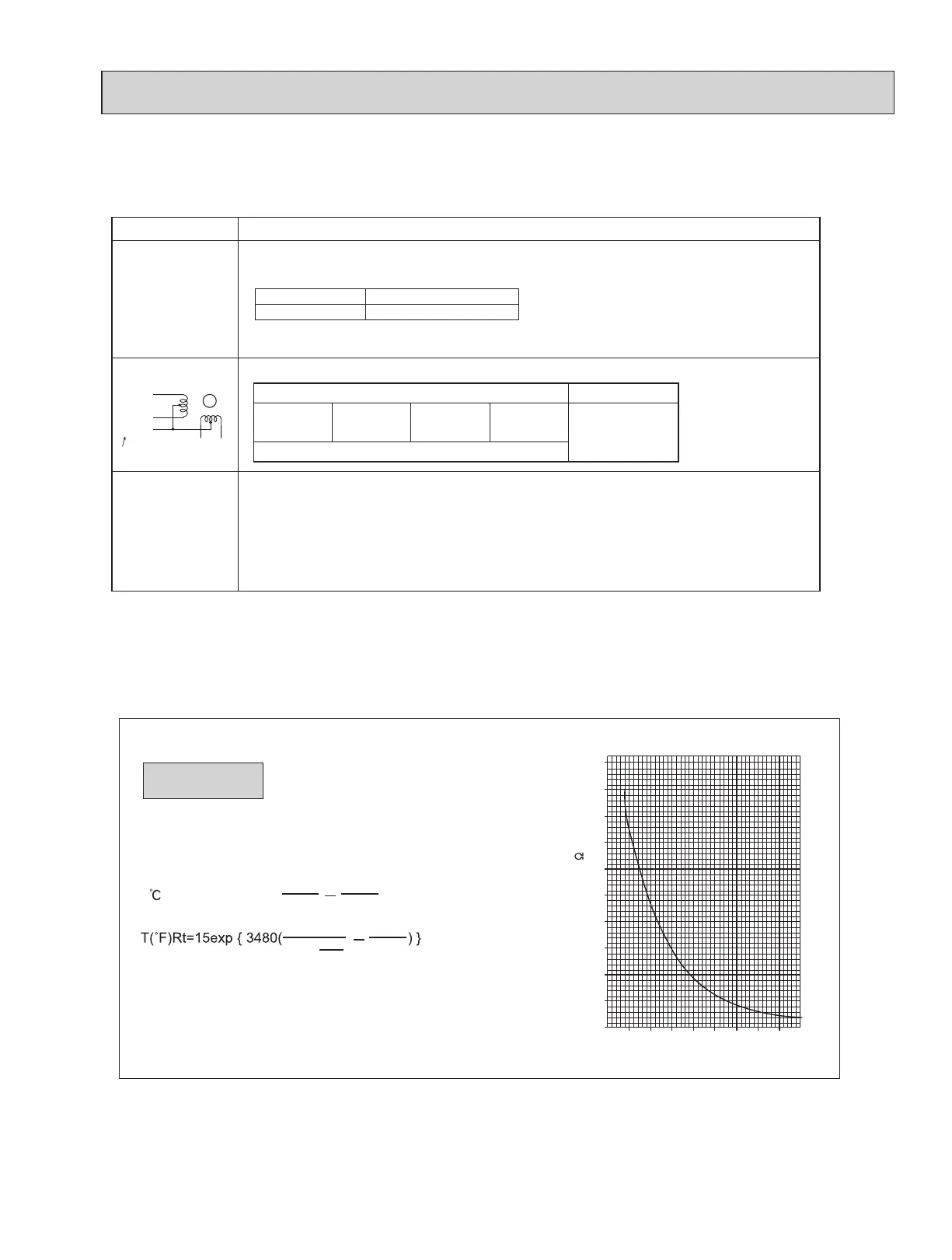
9-6-1. Thermistor
TPKA0A0241KA80A TPKA0A0301KA80A TPKA0A0361KA80A
<Thermistor characteristic graph>
Room temperature thermistor (TH1)
Pipe temperature thermistor/liquid (TH2)
Condenser/evaporator temperature
thermistor (TH5)
Thermistor R
0=15 k ± 3%
Fixed number of B=3480 ± 2%
t(
)Rt=15exp { 3480( ) }
Thermistor for
lower temperature
1
273+t
1
273
0
10
20
30
40
50
-20 -10 0 10 20 30 40 50
-4 -14 32 50 68 86 104122 °F
Temperature
Resistance (k )
<Thermistor for lower temperature>
1
273+
1
273
T-32
1.8
°C
"
32°F [0°C]
50°F [10°C]
68°F [20°C]
77°F [25°C]
86°F [30°C]
104°F [40°C]
15 k"
9.6 k"
6.3 k"
5.4 k"
4.3 k"
3.0 k"
 Loading...