Do you have a question about the Mitsubishi VS-50609 and is the answer not in the manual?
Step-by-step guide for front cabinet removal.
Step-by-step guide for rear cabinet removal.
Procedure to remove the lenticular and fresnel lens components.
Procedure for installing the lenticular and fresnel lens components.
Steps for removing the DiamondShield™ molding clips.
Steps for installing the DiamondShield™ molding clips.
Guide to removing the chassis and identifying PCB locations.
Illustration showing the location of key components on the PCB.
Detailed steps for safely removing the CRT unit.
Detailed steps for safely installing a new CRT unit.
List of required test equipment for electrical adjustments.
Information on test signals like Monoscope and Color Bar.
Procedure for initial setup and default settings of the TV.
Using the power LED for troubleshooting and error code diagnosis.
How to activate and navigate the circuit adjustment mode.
Procedure for raster geometry and convergence adjustments.
Comprehensive list of adjustable items by function.
Diagrams showing test points for various adjustments.
Guidelines for ordering replacement parts.
Information on identifying critical and warranty return parts.
Chart explaining component tolerance codes.
List of model abbreviations used in the manual.
Block diagram of the power supply section.
Block diagram illustrating the video and color signal flow.
Block diagram of the sound circuit.
Block diagram for deflection and high voltage sections.
Block diagram of the protect circuit.
Block diagram of the convergence circuitry.
Block diagram of the control circuit.
| Brand | Mitsubishi |
|---|---|
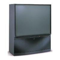
| Model | VS-50609 |
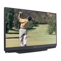
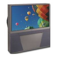
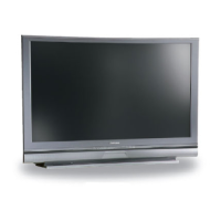
| Category | Projection TV |
| Language | English |