10
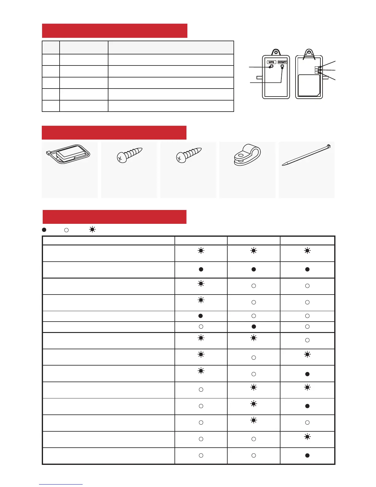
LED pattern
Description LED1 LED2 LED3
Power is ON or software downloaded
(0.5-sec interval) (0.5-sec interval) (0.5-sec interval)
ALL settings reset
WPS activated (PBC)
(0.5-sec interval)
WPS activated (PIN)
(0.2-sec interval)
WPS enabled (5-sec)
WPS failed (5 sec)
Server and access point communication connected, and
heat pump communication failed
(once every 5 sec) (0.5-sec interval)
Server and access point communication connected, and
heat pump communication connected
(once every 5 sec) (once every 5 sec)
Server and access point communication connected, and
heat pump communication starting up
(once every 5 sec)
Server communication failed, and heat pump
communication connected
(0.5-sec interval) (once every 5 sec)
Server communication or access point communication
failed, and heat pump communication starting up
(0.5-sec interval)
Server communication or access point communication
failed, and heat pump communication failed
(0.5-sec interval)
Access point communication failed, and
heat pump communication connected
(once every 5 sec)
Access point communication failed, and
heat pump communication starting up
:ON :OFF :Flashing
Parts
Adaptor unit
[with connecting
cable (5-core)]
Optional screw
for mounting
3.5×16
Optional screw
for mounting
4×16
Optional
mounting cord
clamp
Fastener (for
bundling the
wires)
Product Introduction
No Item Description
1 WPS switch Activates WPS
2 RESET switch Resets the system and ALL settings
3 LED1 (Green) Shows the wireless communication state
4 LED2 (Orange) Shows the MAC-559IF-E state
5 LED3 (Green) Shows the local communication state
2
1
4
3
5

 Loading...


