®
Pro Series Owner’s Manual - Page 9
Testing the Speed Control
NOTE:
The gun should be tested prior to testing circuitry on the main board.
Gun amphenol must be connected to the Cobramatic
®
Pro Series cabi-
net to perform the following tests.
To test the motor voltage circuit and measure how much voltage is being
delivered to the gun motor, place a voltmeter across diode test points TP1
& TP2 and depress gun trigger. A reading between 0 - 30 VDC should be
observed, as the gun potentiometer is varied.
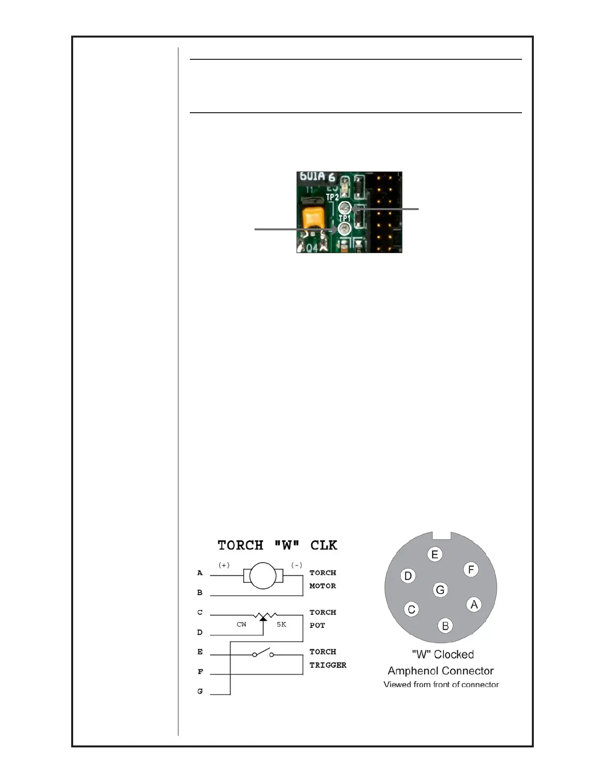
Motor Voltage
Test Point
TP1
Figure 9
Motor Voltage
Test Point
TP2
For reference, see Main PC Board Connections picture in Section F
Testing the Gun
Motor Check
Remove the connector from the cabinet.
Using the Amphenol connector, check the resistance across pins “A” and “B”
(motor leads).
If an open circuit (more than K ohms) or short (less than 2 ohms) exists, check
the motor leads and motor independently.
Testing the Potentiometer - “W” Clocked Amphenol Connector
Using the gun amphenol, check the resistance across pin “D” (wiper) and
pin “C”. The resistance should vary from 0 - 5K ohms as you turn pot..
Check the resistance across pin “D” (wiper) and pin “G”. The resistance
should vary from 5K - 0 ohms as you turn pot.
Testing the Micro Switch
Using the gun amphenol, check for continuity across pins “E” and “F” when
the trigger is pressed.