®
Pro Series Owner’s Manual - Page 26
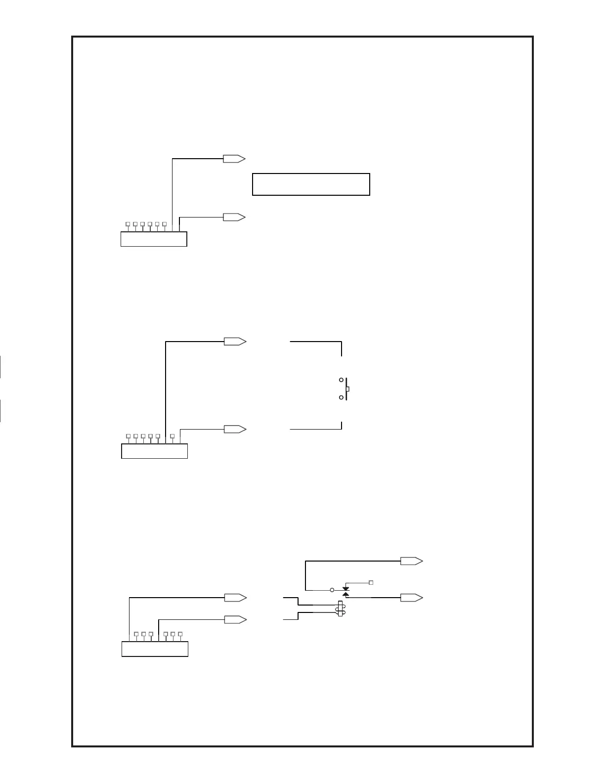
INPUT / OUTPUT CONFIGURATION FOR TB1
Monitor Wire Feed Speed
Use digital volt meter between: TB1 – 1(GND) and TB1 – 2(MSPD).
Measured value defined as: Reading x 100 = Wire Feed Speed.
Example: 3.54 VDC is equivalent to 354 IPM
MSPD
GND
TB1
Remote/External Trigger
Install jumper between: TB1 – 1(GND) and TB1 – 3(TRIG) to trigger system.
TRIG
SW
GND
TB1
Arc Establish Relay Closure
External Contact Signal; Connect 24VDC relay coil between TB1 – 8 (24V)
and TB1 – 4 (ARC). When arc is established, the relay coil will close.
24V
ARC
K?
ARC ESTABLISHED RELAY
ARC ESTABLISHED
ARC ESTABLISHED
TB1
7
6
5
4
3
2
7
6
5
4
3
2
7
6
5
4
3
2