Setup Cha
ter Two: Installation
10
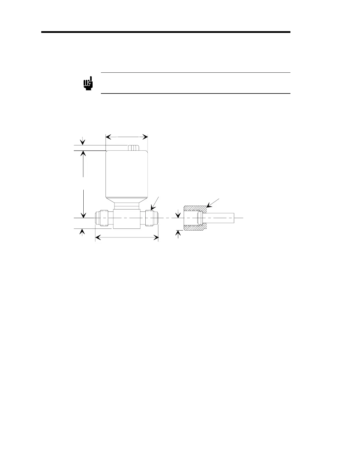
Dimensions of the Flow-Through Units
Note
All dimensions are listed in inches with millimeters referenced in
parentheses.
The dimensions of the flow-through version are the same for high and low pressure units.
1.50 (38.1) Dia
2.45 (62.2)
0.19 (4.8)
0.38 (9.5)
2.25 (57.2)
4-VCR Male Fittin
Matin
4-VCR Connector
(customer supplied)
0.43 (11.0) Ref
Figure 3: Dimensions of Flow-Through Units
Mounting
The 41/42/51/52 switch can be mounted in any orientation with the exception of the low pressure
units (< 20 psi FS). If the full scale pressure of the unit is less than 20 psi
and
the unit may be
exposed to particulates, mount the unit with the connector up. This will allow any foreign matter
entering the unit to fall away from the sensing diaphragm. Material on the diaphragm may cause
a zero shift and reduce the unit's switch point accuracy.