Chapter Two: Installation Interface Cables
15
Special Consideration for the Ground Connection
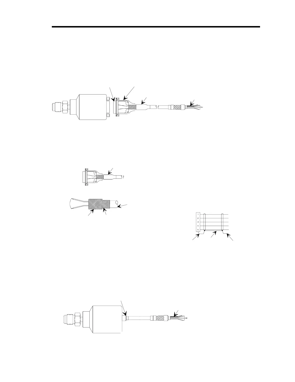
If you choose to make your own cable you must properly ground the cable on both ends to ensure
electromagnetic integrity and compliance with CE regulations. Figure 4 identifies the
components of a cable designed to connect to a Type “D” connector on the pressure switch.
Metal Shell
Type "D" Connector
Heat Shrink Tubing
Bare Metal Shield (Drain) Lead (1)
}
Signal Leads (5)
Figure 4: Components of a Cable to Connect to a Type “D” Connector
On the connector end of the cable, Figure 5 shows how the metal braided shield is folded back
over itself to expose the wires. Then the metal shell of the connector is clamped over the metal
braided shield to form a good contact point.
Type "D"
Connector
Wiring Diagram
Power Return
Power Input
Relay N/O
Relay Common
Relay N/C
Braided
Shield
Cable Outer Jacket
Metal Braided Shield
Notes
1. Build up with heat shrink tubing over outer jacket.
2. Pull metal braided shield over outer jacket.
Refer to Note 1
To User
Connections
}
Bare Metal Shield
(Drain) Lead
Connection made with
the metal shell clamped
over the metal braided shield.
Figure 5: Expanded View of the Cable
At the flying leads end of the cable, connect the shield (drain) lead to the main ground of your
system using the shortest length of shield (drain) lead possible.
Flying Leads Connector
Bare Metal Shield (Drain) Lead (1)
}
Signal Leads (5)
Figure 6: Flying Leads Connector