PART 5: BOILER PIPING (CONTINUED)
I. FILL AND PURGE HEATING SYSTEM
• Attach the hose to balance and purge hose
connector or drain valve and run hose to
nearest drain
• Close the other side of the balance and purge
valve or the shut off valve after the drain.
• Open first zone balance and purge or drain
valve to let water flow out the hose. If zone
valves are used, open the valves one at a
time manually. (Note: You should check valve
manufacturer’s instruction prior to opening
valves manually, so as not to damage the
valve.)
• Manually operate fill valve regulator. When
water runs out of the hose, while it’s
connected to the balance and purge valve or
drain you will see a steady stream of water
(without bubbles). Close balance and purge
valve or drain to stop the water from flowing.
Disconnect the hose and connect it to next
zone to be purged.
• Repeat this procedure for additional zones
(one at time).
Figure 5-2
GAS-FIRED BOILER
Boiler Manual
22
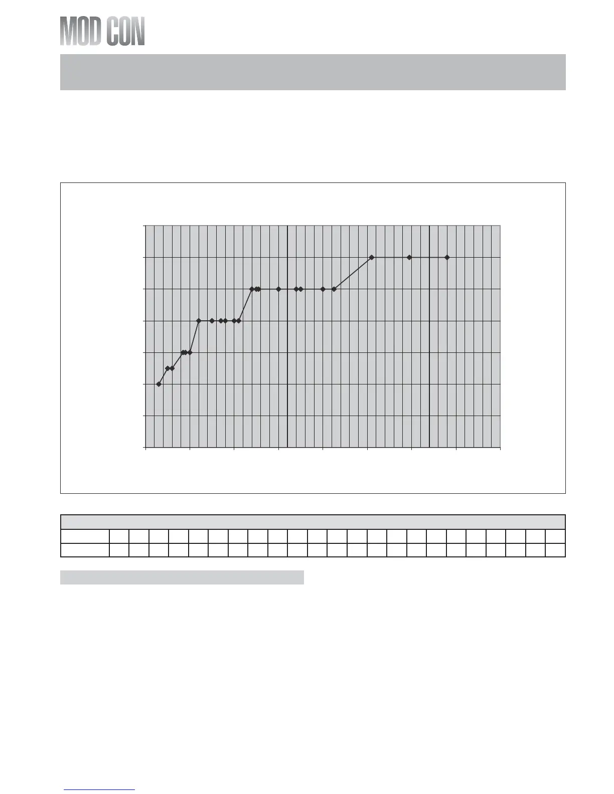
Combined Boiler Pipe Sizing
0
1
2
3
4
5
6
7
0 100 200 300 400 500 600 700 800
Combined Boiler Water Flow (GPM)
Pipe Diameter Size (Inches)
Multiple Boiler Manifold Piping
The chart below represents the combined flow
rates and pipe sizes when using multiple boilers
to design the manifold system for the primary
circuit. To size, simply add up the number of
boilers and the required flow rates for the sys-
tem design temperature.
Example (5) Mod Con 300 Boilers with a design
of 30 degree temperature rise with each boiler
having an individual flow rate of 20 GPM. To cor-
rectly size the manifold feeding these (5) Mod
Con 300 Boilers you would need a pipe size of
3”.
MULTIPLE BOILER MANIFOLD PIPING
Flow rate 30 50 60 85 90 100 120 150 170 180 200 210 240 250 255 300 340 350 400 425 510 595 680
Pipe Dia. 2” 2½” 2½” 3” 3” 3” 4” 4” 4” 4” 4” 4” 5” 5” 5” 5” 5” 5” 5” 5” 6” 6” 6”