12
6-534.1
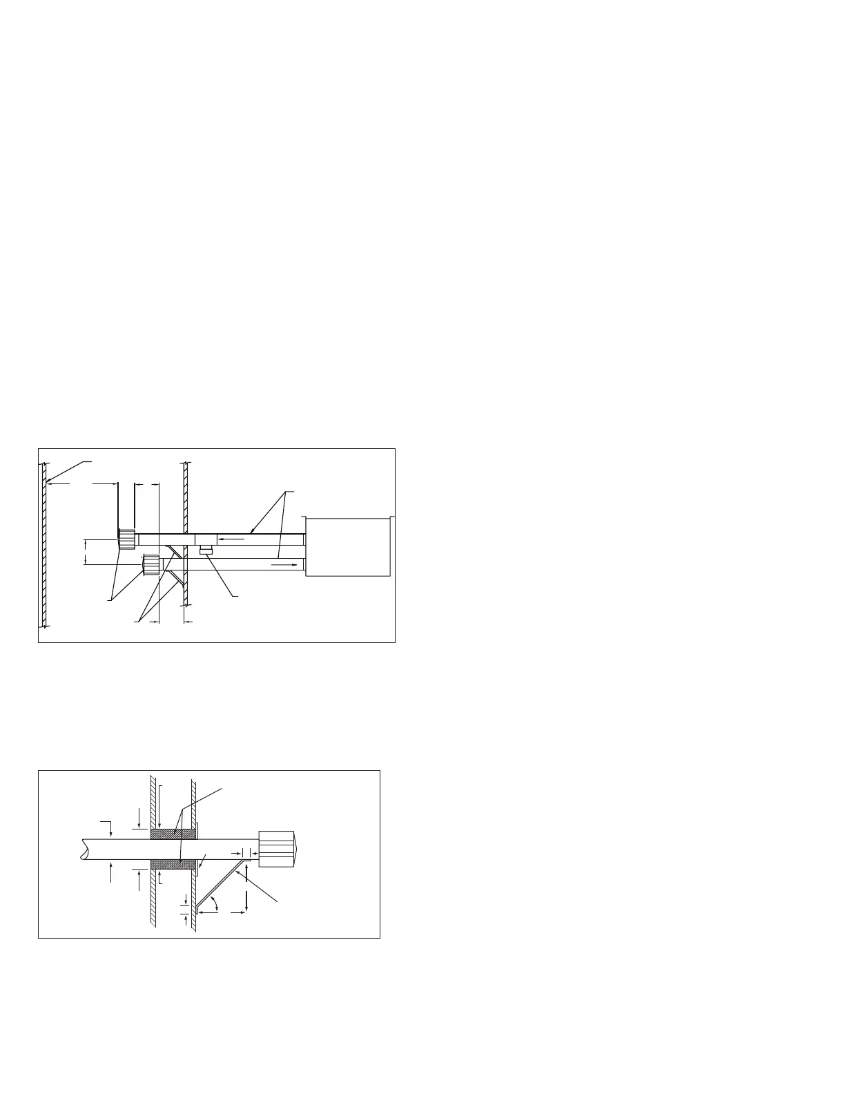
METAL
SLEEVE
FIBER GLASS
INSULATION
MIN. 2"
2" MIN.
VENT TERMINATION
SUPPORT BRACKET
(where required)
(Make from 1" x 1" steel angle)
9"
9"
45
1"
METAL
SLEEVE
2" MIN.
VENT PIPE
DIAMETER
METAL FACE
PLATE
1"
Figure 12.2 - Vent Construction Through
Combustible Walls and Support Bracket
E9. When condensation may be a problem, the vent system
shall not terminate over public walkways or over an area
where condensate or vapor could create a nuisance or
hazard, or could be detrimental to the operation of
regulators, relief openings, or other equipment.
E10. Maintain a 1/4" per foot downward slope away from the
heater and place a drip leg with clean out near the exit of
the vent as shown in Figure 12.2, or allow the condensate
to drip out the end.
E11. For a vent termination located under an eave, the distance
of the overhang must not exceed 24". The clearance to
combustibles above the exterior vent must be maintained
at a minimum of 12". Consult the National Fuel Gas Code
for additional requirements for eaves that have ventilation
openings.
E12. Once venting is complete, proceed to section titled
“Installation - Gas Connections”.
INSTALLATION - VENTING
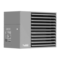
Figure 12.1 - Horizontal Venting with Downward Pitch
COMBUSTION AIR
EXHAUST
SLOPE 1/4" PER FOOT
DOWNWARD FROM UNIT
TEE WITH DRIP LEG AND
CLEANOUT CAP AT LOW
POINT OF VENT SYSTEM
LISTED
TERMINAL
SUPPORT BRACKET
6" MIN
2' MIN
4" MIN
12"
ADJACENT
BUILDING
E7. When horizontal vents pass through a combustible wall
(up to 22" thick), the vent passage must be constructed
and insulated as shown in Figure 12,2.
E8. The vent must be supported as shown in Figure 12.2.
Section E - Horizontal Combustion Air and Vent -
Category III Vent System Determination
(Separated Combustion) Venting Instructions
E1. This section applies to horizontally vented 2-pipe vent
systems (1 combustion air inlet pipe and 1 vent pipe) and is
in addition to “Section A - General Instructions - All Units”.
Category III vent systems listed by a nationally recognized
agency and matching the diameters specified may be used.
Different brands of vent pipe materials may not be
intermixed. Under no circumstances should two sections of
double wall vent pipe be joined together within one horizontal
vent system due to the inability to verify complete seal of
inner pipes.
E2. Horizontal vent systems terminate horizontally (sideways).
E3. All horizontal vents must be terminated with a listed vent
cap. The cap must terminate a minimum distance from the
external wall, as summarized in Figure 12.1.
E4. The termination of horizontally vented system must extend
16" beyond the exterior surface of an exterior wall.
E5. The combustion air pipe must be a minimum of 6" below the
vent pipe, and 4" from the exterior wall.
E6. Construct the vent system as shown in Figure 12.1.
 Loading...