13
6-534.1
INSTALLATION - VENTING
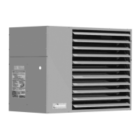
Figure 13.1 - Vertical Concentric Vent Kit
Components
Combustion Air
Inlet Terminal
Outlet Vent
Termination Cap
Building
Roof / Ceiling
Concentric
Vent Adapter
Box
Combustion Air Vent
6" Min.
12" Min.*
* Size according
to expected
snow depth.
CAUTION
The concentric vent adapter box must be installed inside of
the structure or building. Do not install this box on the exterior
of a building or structure.
Section F - Horizontal or Vertical Combustion Air and
Vent Systems using a Concentric Vent - Category III
Vent System Determination (Separated Combustion)
F1. This section applies to both horizontally and vertically
vented concentric vent systems as defined in “Section A –
General Instructions – All Units”, and is in addition to the
instructions in that section.
F2. When utilizing the concentric vent option, it should have
been predetermined whether the appliance will be
horizontally or vertically vented. Before proceeding, verify
that the concentric vent kit received contains the correct
components for the installation:
For Vertical 2 Pipe Vented Units (Refer to Figure 13.1):
Concentric adapter assembly (same for horizontal and
vertical kits)
Standard listed vent cap
Specially designed inlet terminal
For Horizontal 2 Pipe Vented Units (Refer to Figure 13.2):
Concentric adapter assembly (same for horizontal and
vertical kits)
Special vent termination cap
Special air intake guard
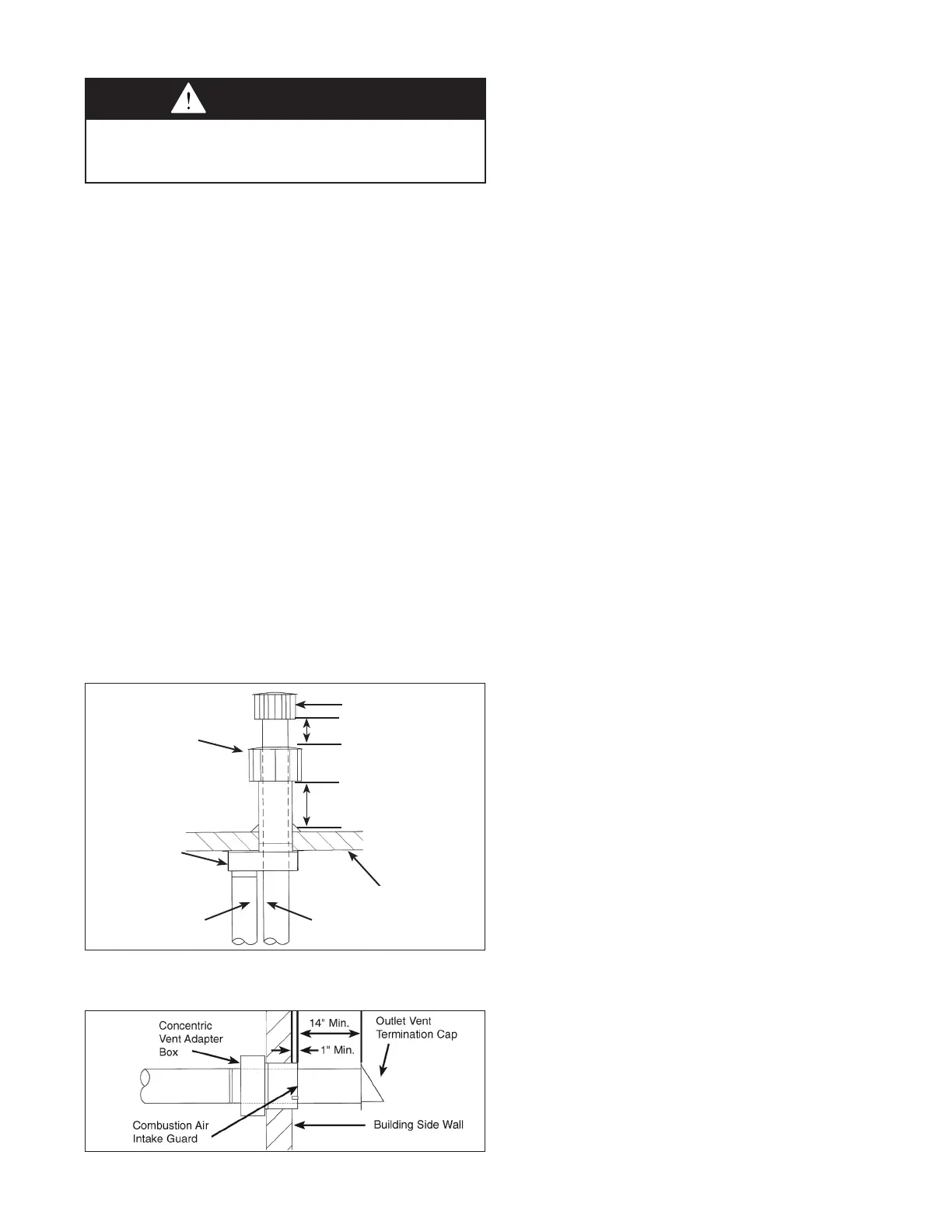
Figure 13.2 - Horizontal Concentric Vent Kit
Components
F3. Once the kit contents have been verified as correct for the
direction of venting, the concentric vent adapter box is to
installed. Determine the location of the box. Be sure to
maintain all clearances as listed in these instructions.
F4. The adapter box is to be mounted on the interior side of
the building. It must not be mounted outside the building.
The adapter box has integral mounting holes for ease of
installation.
F5. The adapter box can be mounted flush to the wall (for
horizontal kits) or to the ceiling (for vertical kits). The box
can also be offset from the wall or ceiling by using field
supplied brackets. When mounting the box, consider
serviceability and access to the vent and combustion air
pipes. If the box is to be mounted using field supplied
brackets, these brackets must be strong enough to rigidly
secure the box to the wall or ceiling, and should be made
from corrosion resistant material.
F6. Determine the length of the vent pipe and combustion air
inlet pipe for the selected location. THE VENT PIPE WILL
PASS THROUGH THE CONCENTRIC VENT BOX. THE
LAST SECTION OF VENT PIPE IS A CONTINUOUS
LENGTH OF DOUBLE WALL “B” VENT. See section A11
for attaching and terminating double wall pipe. Begin with
pipe lengths on the concentric pipe side of the concentric
vent kit, referring to Figure 14.1. These pipes will extend
through the building wall or roof as well as any added
length for the thickness of the wall and the offset from any
field installed brackets.
For Vertical Concentric Vent Kits
(Refer to Figure 13.1):
• The bottom of the combustion air intake pipe must
terminate above the snow line, or at least 12" above
the roof, whichever distance is greater.
• The bottom of the vent cap must terminate at least 6"
above the top of the combustion air intake cap.
For Horizontal Concentric Vent Kits
(Refer to Figure 13.2):
• The combustion air intake pipe must terminate at least
1" from the wall to prevent water from running down the
wall and into the pipe.
• The back of the vent cap must terminate at least
14" from the combustion air intake pipe.
F7. Cut the concentric side vent and combustion air pipes to
the proper length as determined in the previous step. See
Table 14.1 for combustion air and vent pipe sizes. The
pipes must be single wall galvanized or stainless steel
material, except for the last section of vent pipe, which
must be one continuous length of double wall B-vent
extended through the concentric vent box and combustion
air inlet pipe on the concentric side of the box.
NOTE - No clearance to combustible material is required
for the building penetration, which should be sized according
to the external combustion air Inlet pipe diameter.
F8. Allow the concentric side vent pipe to pass through the
concentric vent adapter box, as shown in Figure 14.1.
Attach the double wall vent pipe to the single wall vent
pipe that goes to the unit. Be sure to seal the joint and the
open area around the double wall vent. Seal all joints and
seams using sealant suitable for temperatures up to 400°F.
 Loading...