14
6-534.1
INSTALLATION - VENTING
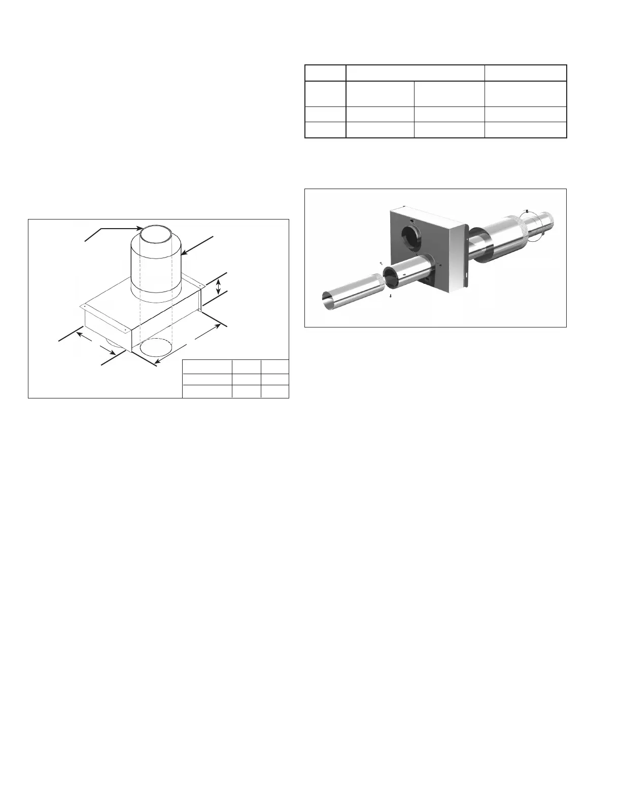
Table 14.1 - Concentric Vent Pipe Sizes
Figure 14.2 - Concentric Vent Kit Exploded Assembly
Single Wall Pipe
Type B Vent Pipe
Model Size
Combustion Air (To
Unit)
Combustion Air
(External)
Vent
(Pass-Through)
150-200
4" 6" 4"
250-400
6" 8" 6"
B-Vent must have 1/4" air gap (OD is 1/2" larger than ID).
F9. Slide the combustion air pipe over the vent pipe and
attach to the air inlet of the concentric adapter box, as
shown in Figure 14.1, using at least 3 corrosion-resistant
sheet metal screws. Seal the joint and seam using sealant
suitable for temperatures up to 400°F.
F10. Place this assembly (the adapter box, vent pipe and
combustion air pipe) through the wall or roof and verify
that the distance requirements as defined in Step F7 are
met. Securely attach the assembly to the building.
F11. From outside the building, caulk the gap between the
combustion air intake pipe and the building penetration.
F12. Attach the combustion air intake and vent pipe
terminations as follows:
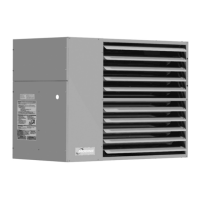
Figure 14.1 - Concentic Vent kit with Combustion Air
Intake Pipe Attached
Outlet Vent
Pipe Extended
Through Box
Combustion Air
Pipe Attached
A
B
4.57"
Model Sizes A B
150-200 13.33" 18.84"
250-400 17.00" 15.27"
For Vertical Concentric Vent Kits
(Refer to Figure 13.1):
• Slide the combustion air cap down over the vent pipe
and fasten it to the combustion air pipe with at least
3 corrosion-resistant sheet metal screws.
• Attach the vent cap to the vent pipe using at least
3 corrosion-resistant sheet metal screws. Refer to
instruction A11 for connecting terminal to double wall
pipe.
• Caulk the gap between the combustion air cap and the
vent pipe with silicone sealant, or other appropriate
sealants suitable for metal to metal contact and for
temperatures up to 400° F.
For Horizontal Concentric Vent Kits
(Refer to Figure 13.2):
• Attach the combustion air intake guard using corrosion-
resistant screws at the end of the combustion air intake
pipe to prevent animals and debris from entering.
• Attach the vent cap to the vent pipe using at least
3 corrosion-resistant sheet metal screws.
F13. Install vent pipe and combustion air pipe between unit
heater and concentric vent adapter box as outlined in
“Section A – General Instructions – All Units”.
F14. Once venting is complete, proceed to the section titled
“Installation - Gas Connections”.
 Loading...