Cutting The Hole - For THIN Wall Installation (3/16”
thickness or less)
1. Repeat step 1, as in the section ‘Cutting The Hole - For
THICK Wall Installation.’
2. Following the shape just traced, draw a line following this
shape 1/8” to 1/4” inside this shape. This inner line defines
the shape which must be cut out.
Attach The Mounting Bracket
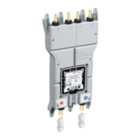
1. A metal mounting bracket is provided to mount the valve to the wall
studs.
2. The bracket must first be attached to the valve as follows:
• The bracket is attached to the valve at the two screw holes
located beneath the central portion of the valve.
• Place the flat side of the bracket against these two screw holes
on the valve with the center curved flange on the bracket in the
up position.
• Fasten the bracket to the valve using the two screws provided,
passing through the two slots in the bracket and into the two
screw holes on the valve. Tighten the screws loosely at this time.
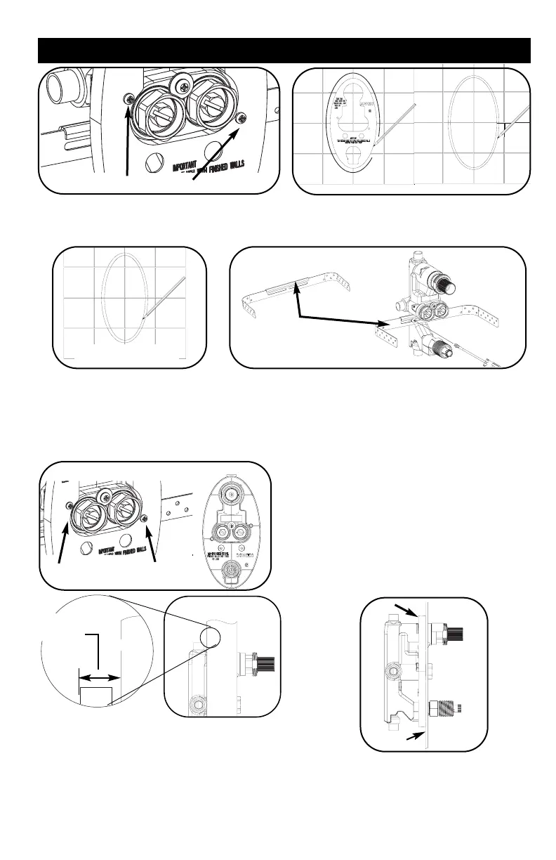
Cutting The Hole - For THICK Wall Installation (3/16” to
2” thickness)
1. Remove the plaster ground from the valve and save the screws
(required for thick wall install). Trace the shape of the plaster
ground on the wall (use a pencil that can be washed off).
2. Following the shape just traced, draw a line 1/16” to 3/16”
outside this shape. This outer line defines the shape which
must be cut out.
Remove the two plaster ground screws
INSTALLATION INSTRUCTIONS
Trace outer line 1/16” to 3/16” from
the inner sketched line.
Center Curved Flange
The bracket comes pre-bent, as shown.
Reinstalling The Plaster Ground
1. For THICK wall, use the two screws (18) to re-install the black
plaster ground (17) to the front of the valve.
2. For THIN wall, Place the plaster ground back on the valve with
the flat face of the plaster ground against the valve (this is the
opposite side from the original attachment). Do not re-attach
screws.
Re-attach the plaster ground (17)
using the plaster ground screws (18).
THICK wall THIN wall
Trace inner line 1/8” to 1/4” from
the sketched outer line
Valve Positioning For Thin Walls
Place the valve with plaster ground behind the finished wall
such that the plaster ground is centered on the wall cut-out.
The outer edge of the plaster ground should be positioned
against the back side of the thin wall. This is required to
support the thin wall.
17
Thin wall
1/2” min. for copper
piping (5/8” min. for IPS
threaded)
Thick wall
2” max.
{
Valve Positioning For Thick Walls
1. Wall thickness should not exceed 2” max.
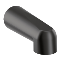
2. Ensure that there is at least 1/2” clearance (5/8” for IPS connections)
between the wall and the center of the tubspout/showerhead outlets.
3. The black oval shaped plaster ground should be located flush to 1/8”
recessed relative to the outside of the finished wall.
4. Note that if the exact location of the finished wall is not known, the
two handles which will attach to the valve will accommodate an
inaccuracy of a +1/2” thicker, or a -3/8” thinner wall.