28. A djust the side rollers on the transverse beams so that they just contact the sides of
the posts.
NOTE: This is not applicable to the “WHEEL-FREE” models.
29. A djust the limit switch actuating bracket so that it clears the No. 1 Post by
approximately 2mm.
Adjust the limit switch so that the hoist automatically stops before the safety
toggle rollers reach the wire rope ends.
30. F it the run-up ramps at the drive-on end, and the wheel stops at the other end of
the platforms.
NOTE: “WHEEL-FREE” models only. Bolt the run-up ramp locating bar in position and
fit the other section of the run-up ramps. Fit the run-up ramp extensions. Fit the
two WHEEL-FREE RAILS so that they rest on the secondary transverse beams.
31. D ouble check that all wire ropes are properly seated on the pulleys, (refer layout
of wire ropes) and that the hoist is operating correctly.
Double check that the wire ropes are not crossing each other.
FITTING OF JACK STAND AND JACKING BEAMS JB87
32. F it The Jack Stand (and Jacking Beams
“JB87”, (if purchased).
NOTE: Remove 3 of the 4 countersunk bolts
holding the secondary platform (platform
adjacent to NO. 2 and No. 4 posts) in
position. Slide the platform outwards, place
the Jack Stand (and Jacking beams) into
position. Slide the platform into the original
position.
Re-bolt the platform with the 3 countersunk bolts.
33. Clean the hoist of anti-corrosion spray.
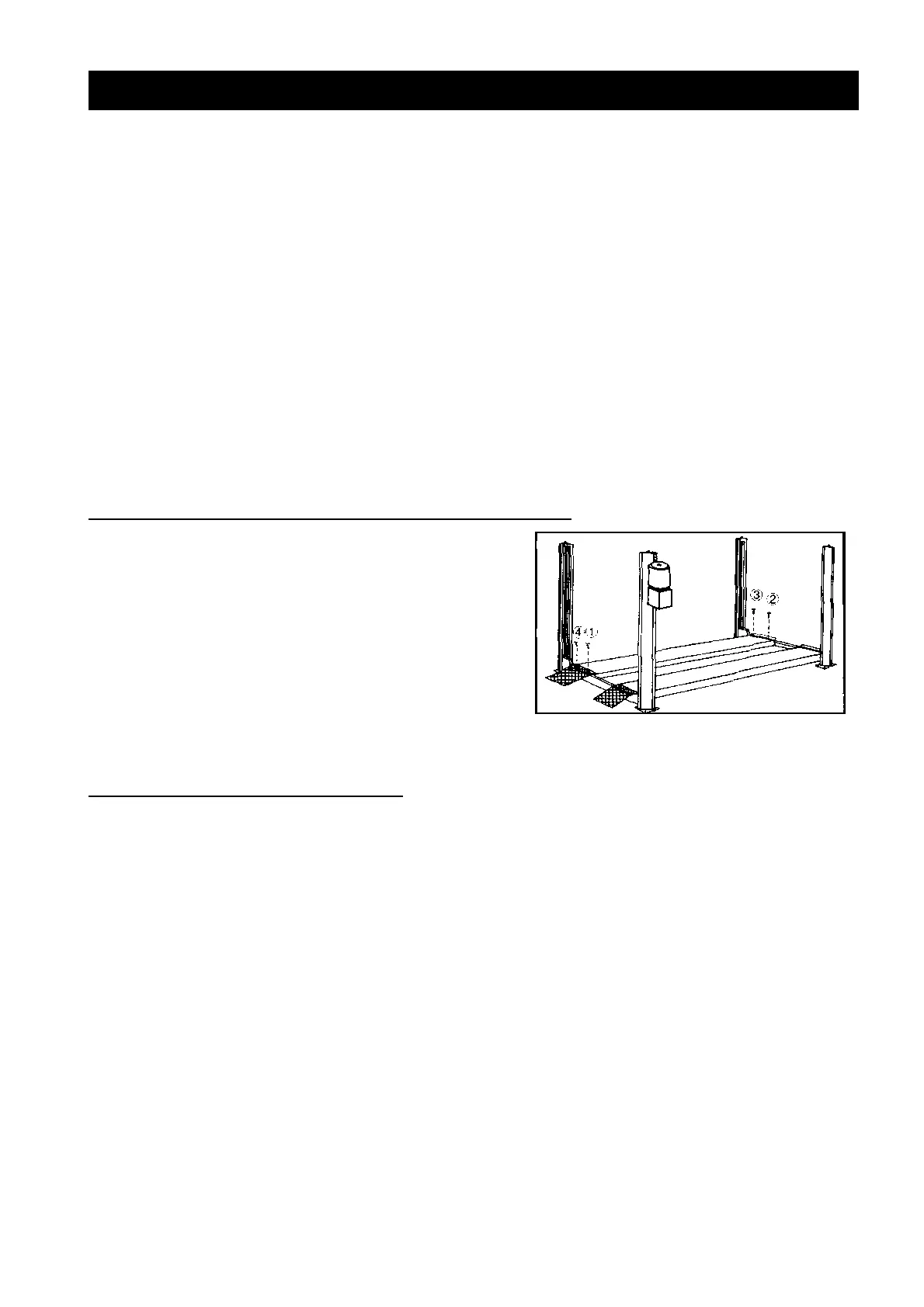
FITTING OF DRIP TRAY 44880DRPT
34.(1). Raise hoist to normal working height, engage safety locks and lower until hoist
is just resting on the safety locks.
(2). Orientate Drip Tray so the Support Tabs are on the top and slide Drip Tray over
the top of the Ramp Brace Strap. Refer to Figure 21 on page 23, steps 1, 2 & 3.
(3). Locate Drip Tray in the cavity created by the inside edges of the ramp, the
Ramp Brace Strap and the Cylinder Support Strap. Refer to steps 4 & 5.
(4). Push down on the Support Tabs to ensure the bottom of the drip tray protrudes
slightly below the bottom of the Straps. Refer to step 6. It is important that the
top of the Drip Tray is pushed down as low as possible for there is little clearance
from the top of the Straps and the bottom of the Cable Block. The Drip Tray is in
danger of being crushed by the Cable Block if the top of the Drip Tray is too high.
(5). Check Drip Tray clearance by slowly lowering the hoist until Cable Block travels
over the area of the Drip Tray. If the Cable Block touches the Drip Tray repeat
step 4.
(6). Installation is complete.