1. Cut the tube to length and file ends square.
2. Remove internal and external burrs from tube end.
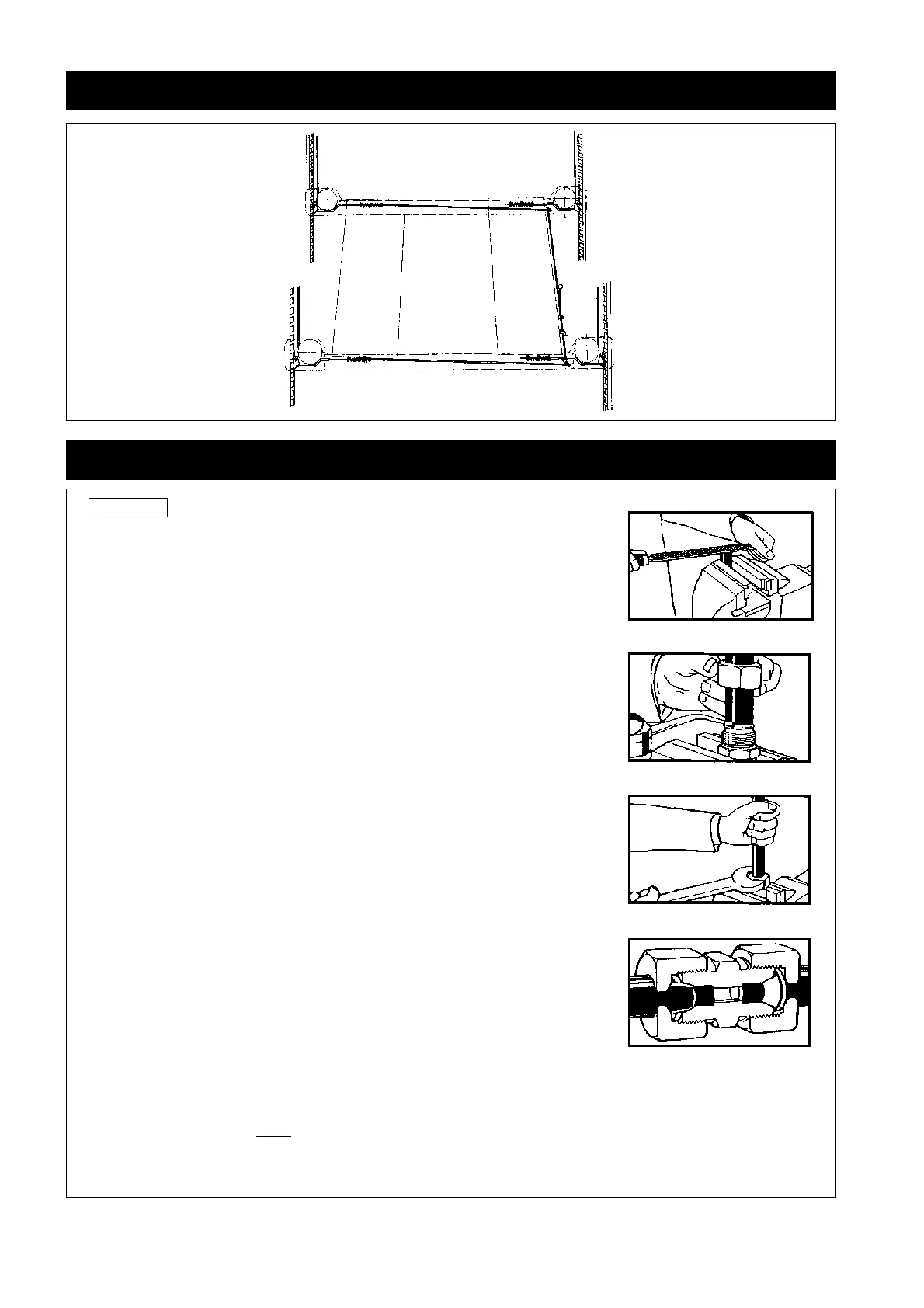
3. We always highly recommend that joints are pre-made whilst the
coupling body is held firmly in a bench vice.
4. Ascertain that all the detail parts of the coupling are suitably
lubricated, especially the internal body cone, the rear of the
ferrule and the internal thread of the nut. The lubrication process
is recommended on all fittings, however, on stainless steel
couplings the use of a quality lubricant is imperative. Betalube,
a copper based paste is highly recommended and available
from Betabite Hydraulics or your local distributor. Please note
after assembly, fittings to be used on Oxygen lines should be fully
degreased.
5. Slide the nut onto the tube, followed by the ferrule, the open
end of the nut should be towards the end of the tube, and
similarly, the cutting or smaller end of the ferrule should point
towards the tube end.
6. Present the tube, nut and ferrule to the coupling body, making
sure that tube passescleanly through the nut and ferrule & butts
firmly against the step (abutment face) provided in the coupling
body. Screw the nut onto the coupling body until finger tight.
7. Hold the tube in one hand and with the correct sized spanner in
the other hand, tighten the nut until the ferrule is felt to just grip
the tube. This point is determined by rotation or slightly rocking
the tube. From this point, the nut should be tightened 1 ¼ to 1
½ turns from the initial ring grip to obtain a fully effective cutting
action. On larger sizes of fitting, an extension to the spanner is
highly recommended to maximise leverage and minimise effort.
8. If the nut is now removed, the ferrule will have cut its own seating
on the tube and whilst it will be found to rotate, it cannot be
moved towards the tube end. The 'joint' may now be re-assembled, by re-tightening of the
nut until significant resistance is felt and then increase for a further
1
/8 to ¼ of a turn. The
above procedure must be followed closely to ensure a safe and successful joint.
9. Betabite fittings correctly made can be broken repeatedly, when not under pressure and
re-made without affecting their pressure tightness and leak-proof quality.
Page 20
GENERAL LAY O UT OF LOCKING MECHANISM