INSTALLATION WIRING DIAGRAM
lW
VAC
60
HZ
3A
MAX.
(SUPERVISED)
Ill
(GREEN)
AC
PILOT
SUPERVISORY
CURRENT
MILLIMIMETER
0.10 MA.
(RED)
ALAN
(AMBER)
ALARM
SUXNCED
OXHll'E)
TROUBLE
0
AC
PRI
MODEL
C-99A-24
FIRE ALARM CONTROL
. .
(YELLOW)
TROUBLE
SILENCE
'",%?
(WHITE)
TEST
fi
&
NORMAL
&
NOPMAL
&
NORM-
4
4
SILENCE
RESET
TEST
-
+
ALARM
MODE POLARITY
CABINET
WOR
-I-
-
SUPERVISORY
MODE
POLARITY
I
SILENCE)
I,~&",L~,"X,
I$EM%zN
MAX.
CURRENT
I00
MA.
(500
NO. I4
AWG)
SUITABLE
FOR
AT
24
VDC CONNECIION
TO
REFER
10
TO
NOTE
DEVICE
INDICATED
IN
NOTE
4
NOTES:
(SUPERVISED)
(SUPERVISED
LIMITED
ENERGY
CIRCUIT1
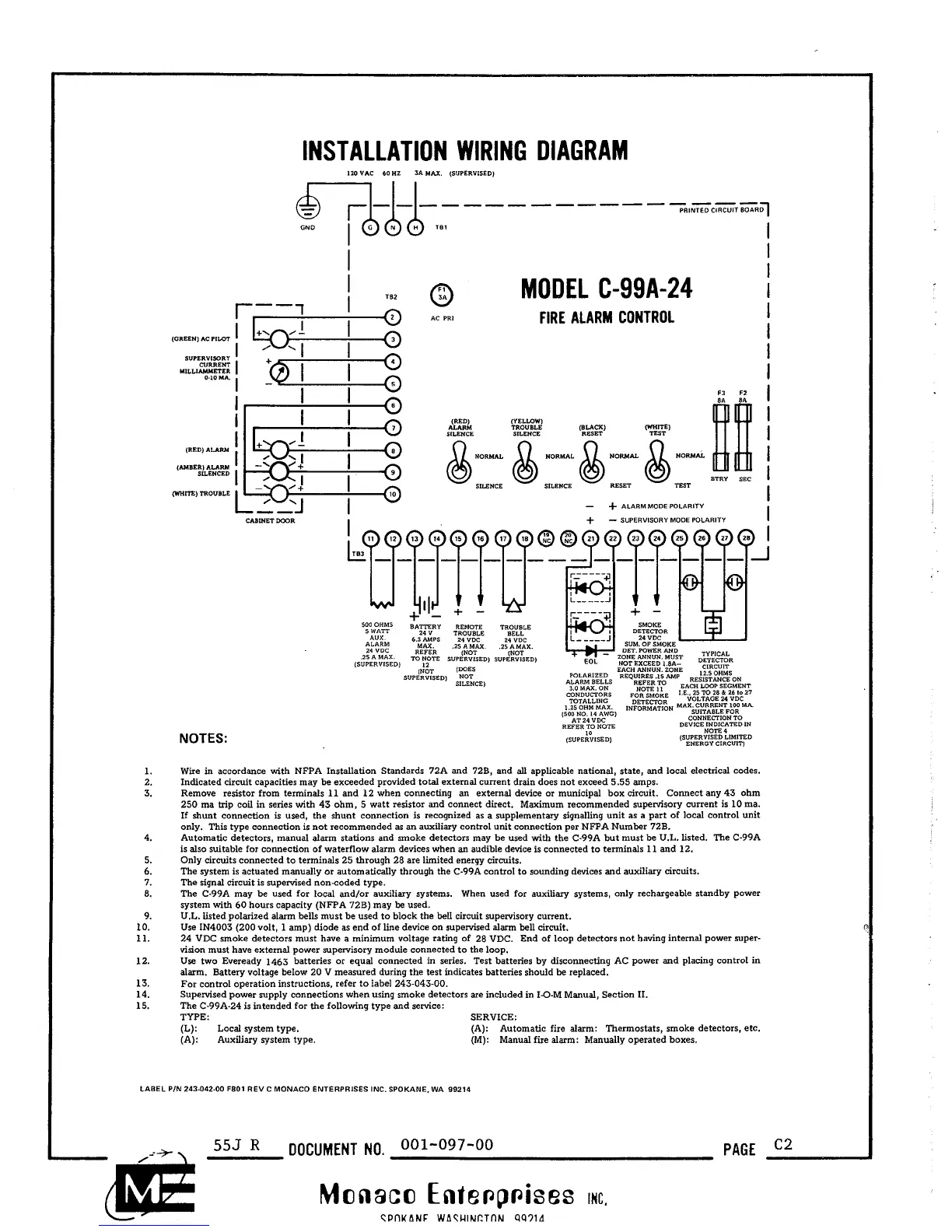
Wire in accordance with NFPA Installation Standards 72A and 728, and all applicable national, state, and local electrical codes.
Indicated circuit capacities may be exceeded provided total external current drain does not exceed
5.55
amps.
Remove resistor from terminals
11
and 12 when connecting an external device or municipal box circuit. Connect any 43 ohm
250 ma trip coil in series with 43 ohm,
5
watt resistor and connect direct. Maximum recommended supervisory current is 10 ma.
If shunt connection is used, the shunt connection is recognized as a supplementary signalling unit as a part of local control unit
only. This type connection is not recommended as an auxiliary control unit connection per NFPA Number 72B.
Automatic detectors, manual alarm stations and smoke detectors may be used with the C-99A but must be U.L. listed. The C-99A
is also suitable for connection of waterflow alarm devices when an audible device is connected to terminals
11
and 12.
Only circuits connected to terminals 25 through 28 are limited energy circuits.
The system is actuated manually or automatically through the C-99A control to sounding devices and auxiliary circuits.
The signal circuit is supervised non-coded type.
The C-99A may be used for local
and/or auxiliary systems. When used for auxiliary systems, only rechargeable standby power
system with 60 hours capacity (NFPA 72B) may be used.
U.L. listed polarized alarm bells must be used to block the bell circuit supervisory current.
Use IN4003 (200 volt,
1
amp) diode
as
end of line device on supervised alarm bell circuit.
24 VDC smoke detectors must have a minimum voltage rating of 28 VDC. End of loop detectors not having internal power super-
vision must have external power supervisory module connected to the loop.
Use two Eveready 1463 batteries or equal connected in series. Test batteries by disconnecting AC power and placing control in
alarm. Battery voltage below 20 V measured during the test indicates batteries should be replaced.
For control operation instructions, refer to label 243-043-00.
Supervised power supply connections when using smoke detectors are included in I-0-M Manual, Section 11.
The C-99A-24 is intended for the following type and service:
TYPE: SERVICE:
(L):
Local system type. (A): Automatic fire alarm: Thermostats, smoke detectors, etc.
(A): Auxiliary system type. (M): Manual fire alarm: Manually operated boxes.
LABEL PIN 243.04240 F801 REV
C
MONACO ENTERPRISES INC. SPOKANE. WA 99214
555
R
DOCUMENT
NO.
001-097-00
PAGE
C2
Monaco
Ente~pises
Inc.
CPnKANF WACUINCTflhl
99714
 Loading...