7
Italiano
Italiano Pagina
Indice
Español
Español Página
Contenidos
Nederlands
Nederlands Pagina
Inhoud
Polski
Polski Strona
Spis treści
English
Contents
1 Applications . . . . . . . . . . . . .7
2 Operating Elements
and Connections . . . . . . . . . . 7
2.1 Front panel . . . . . . . . . . . . . . 7
2.2 Rear panel . . . . . . . . . . . . . . 7
3 Safety Notes. . . . . . . . . . . . .7
4 Caution with High Volumes . . . . 7
5 Installation . . . . . . . . . . . . . 7
6 Connection of the
Power Amplifier. . . . . . . . . . .8
6.1 Power supply . . . . . . . . . . . . . 8
6.1.1 Operating voltage . . . . . . . . . 8
6.1.2 Ground connection. . . . . . . . .8
6.1.3 Control voltage for switching-on . . 8
6.2 Inputs. . . . . . . . . . . . . . . . .8
6.2.1 4-channel operation (fig. 3). . . . .8
6.2.2 Active 2-way operation (fig. 4) . . . 8
6.2.3 Bridge operation (fig. 5) . . . . . . 8
6.2.4 3-channel operation (fig. 6). . . . .8
6.3 Line output . . . . . . . . . . . . . . 8
6.4 Speakers . . . . . . . . . . . . . . . 8
6.4.1 4-channel operation . . . . . . . . 8
6.4.2 Active 2-way operation . . . . . . .8
6.4.3 Bridge operation . . . . . . . . . . 8
6.4.4 3-channel operation . . . . . . . . 8
7 Setting into Operation . . . . . . . 9
7.1 Selecting the filters and adjusting the
crossover frequencies . . . . . . . . .9
7.2 Adjusting the level and
thebassboosting . . . . . . . . . . .9
8 Troubleshooting. . . . . . . . . . .9
9 Specifications . . . . . . . . . . . . 9
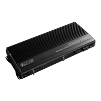
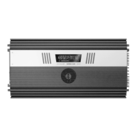
4-Channel Car HiFi
PowerAmplifier
These instructions are intended for experts
with knowledge in the electrical system of
cars (all chapters) and users without any spe-
cific knowledge (chapters 3 and 4). Please
read the instructions carefully prior to instal-
lation and keep them for later reference.
All operating elements and connections
described can be found on the fold-out
page3.
1 Applications
The power amplifier HPB-604 has especially
been designed for car HiFi systems and is able
to drive four full range speakers (2-way or
3-way speakers). Due to the integrated cross-
over networks, it is also possible to implement
an active 2-way system with two mid-high
range speakers and two bass speakers or a
subwoofer (bi-amping).
To obtain a higher output power, the
channels 1, 2 and / or 3, 4 can drive one 4 Ω
speaker each in bridge operation.
2 Operating Elements
and Connections
2.1 Front panel
1 RCA jacks CH 1 and CH 2 for the input
signals of the channels 1 and 2
2 RCA jacks CH 3 and CH 4 for the input
signals of the channels 3 and 4
3
Trimming controls LEVEL for input level
matching:
upper control for the channels 1 and 2,
lower control for the channels 3 and 4
4
Trimming controls BASS EQ for bass boost-
ing up to 12 dB at 50 Hz:
upper control for the channels 1 and 2,
lower control for the channels 3 and 4
5
Trimming controls HP for adjusting the
crossover frequency of the high pass:
upper control for the channels 1 and 2,
lower control for the channels 3 and 4
6
Trimming controls LP for adjusting the
crossover frequency of the low pass:
upper control for the channels 1 and 2,
lower control for the channels 3 and 4
7
CROSSOVER switches for selecting the
filters:
upper switch for the channels 1 and 2,
lower switch for the channels 3 and 4
FULL for full range speakers, no filter
switched on
LP for bass speakers or a subwoofer,
low pass switched on
HP for mid-high range speakers, high
pass switched on
8 Switch for the operating mode
“2” for active 2-way operation: only
connect the inputs 3 and 4 (fig. 4),
channel 1 receives the signal from
input 3 and channel 2 from input 4
“3” 3-channel operation: channels 1
and 2 operate separately, channels
3 and 4 are used in bridge operation
to drive a subwoofer (fig. 6)
“4” 4-channel operation: each channel is
driven via an individual input (fig.3)
9
Line jacks OUTPUT for connection of a
subwoofer amplifier or for connection of
the inputs 3 and 4 (fig. 6)
The fed-through input signal of the inputs
1 to 4 is available in mono at both jacks.
2.2 Rear panel
10 Ground terminal GND
11
Control input REM for switching on the
power amplifier via a 12 V voltage supply
12 Connection for the supply voltage +12 V
13 Fuses 2 × 25 A
Only replace a blown fuse by one of the
same type!
14 POWER LED
15 LED PROT. lights up when the protective
circuit has been activated:
1. if a short circuit has occurred at one of
the speaker outputs (16)
2. if the power amplifier is overheated
16 Terminals SPEAKER
3 Safety Notes
The power amplifier corresponds to all rel-
evant directives of the EU and is therefore
marked with .
•
Be very careful when connecting the car
HiFi power amplifier to the battery. Risk of
short circuit and dangerous high voltage!
Therefore, always screw off the negative
terminal from the car battery prior to con-
necting the power amplifier.
•
The power amplifier must be installed at
a mechanically stable place in the car. It
must be skilfully fixed so that it does not get
loose and turn into a dangerous projectile.
•
During operation, the unit may become
very hot. Therefore, do not place any ob-
jects sensitive to heat near the unit and
do not touch the power amplifier while in
operation.
•
For cleaning only use a dry, soft cloth; never
use chemicals or water.
•
No guarantee claims for the unit and no
liability for any resulting personal damage
or material damage will be accepted if the
unit is used for other purposes than orig-
inally intended, if it is not correctly con-
nected or operated, or if it is not repaired
in an expert way.
If the unit is to be put out of oper-
ation definitively, take it to a local
recycling plant for a disposal which
will not be harmful to the environ-
ment.
4 Caution with High Volumes
•
Never adjust a very high volume. Extremely
high volumes may damage your hearing.
•
Your ear will accustomed to high volumes
which do not seem to be that high after
some time. Therefore, do not increase a
high volume after getting used to it.
•
While driving in the car, signal sounds, e. g.
by an ambulance, must not be drowned by
the car HiFi system which has been set to a
very high volume.
•
With the motor switched off, the car HiFi
system should not be in operation at high
volume for a longer period of time. The car
battery will quickly be discharged and may
not be able to supply sufficient energy for
starting the car.
5 Installation
When choosing the place of installation,
always observe the following:
•
The 12 V power supply cable from the bat-
tery to the car HiFi power amplifier should
be as short as possible. It is better to use
longer speaker cables and a shorter power
supply cable instead.
•
The ground cable from the power amplifier
to the chassis of the car should also be as
short as possible.
•
Sufficient air circulation is required to dissi-
pate the heat generated by the car HiFi power
amplifier.
English
English Page
Contents

 Loading...