11
English
4321
ON
ON
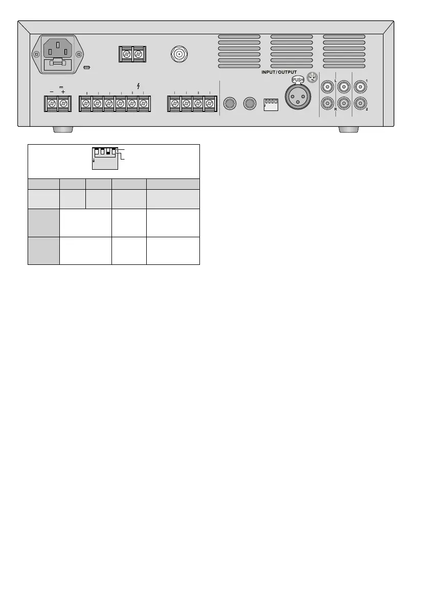
No. 1 2 3 4
for
input
CH 2 CH 3 CH 1
CH 1 and
TELINPUT
Position
OFF
Mikrophone
level
phantom
power
OFF
CH 1 has
highest priority
Position
ON
line level
phantom
power
ON*
TEL INPUT has
highest priority
*Important: When phantom power has been acti-
vated, do not connect any microphone or audio unit
with unbalanced output signal to the input CH1; the
microphone/audio unit may be damaged.
Note: When announcements are being made via
the channels CH 2 and CH 3, the signals of the music
module and of the inputs CH 4 and CH 5 will be
slightly attenuated.
2) To connect audio sources with line level out-
put (e. g. CD player, mixer), use the following
jacks:
– RCA jacks CH 4 and CH 5
– 6.3 mm jacks CH 2 and CH 3
Note: The inputs CH4 and CH5 are provided with
a pair of jacks for the connection of audio stereo
sources. The amplifier will create a mono signal from
the stereo signal. To connect stereo audio sources to
the inputs CH 2 and CH 3, use a stereo/mono adapter
(e. g. SMC-1).
When connecting the audio sources to the
jacks CH 2 and CH 3, set the DIP switches1
and 2 to the position ON (also see table).
3)
For important (emergency) announce-
ments, use the input TEL INPUT. It is possible
to connect, for example, a telephone system
with line level output to this input.
Note: A signal at the input TEL INPUT will mute all
other channels. When DIP switch 4 is in the position
OFF, however, announcements made via the input
CH 1 will have highest priority and will also mute the
channel TEL INPUT.
4)
Connect a DAB / FM antenna to the jack
ANTENNA. With good reception conditions,
the wire antenna provided can be used.
5) If it is necessary to mute the speaker out-
puts, connect the two MUTE terminals, e. g.
via a switch.
3.2 Outputs
1)
Speakers: Either connect 100 V or 70 V
speakers to the terminals “100V” or “70V”
and “COM” (page 2, fig. 1). The load by
the speakers must not exceed the power rat-
ing of the amplifier (chapter 5); otherwise, the
protective circuit will interrupt the connection
to the speaker terminals.
Or connect a speaker or a speaker group to
the terminals “4 Ω”, “8 Ω” or “16 Ω” and
“COM”. The total impedance of the speakers
must not fall below the value indicated at the
terminal used. Figure 2 on page2 shows
various ways to observe the minimum imped-
ance. There are, however, also other possi-
bilities.
2)
At the RCA jacks REC OUT 1 and 2, the mixed
signal is available. The control MASTER will not
have any effect on the volume of this signal.
The jacks can also be used, for example, for
a recorder or additional PA amplifiers if
more speakers are required than PA-806DAP
can handle.
3) The output MOH OUTPUT (music on hold) is
able to provide, for example, music on hold for
a telephone system. The mixed signal is also
available at this output. The control MASTER
will not have any effect on the volume.
USE ONLY WITH A 250V FUSE
4321
ON
+
+
12
3
230 V~
50 Hz
FUSE
24 V
COM 4 Ω 8Ω 16Ω 70 V 100V
SPEAKER OUTPUT
COM COM
TEL INPUT
600Ω/100mV 600Ω/1V
MOH OUTPUT
CH
2 CH
3
SELECT
ON
OFF
1
ON
-
CH 2 LINE
OFF
-
CH 2 MIC
1
ON
-
CH 3 LINE
OFF
-
CH 3 MIC
2
ON
-
PH. POWER CH 1 ON
OFF
-
PH. POWER CH 1 OFF
3
ON
-
PRIO. TEL
OFF
-
PRIO. CH 1
4
2 3 4
CH
1
ANTENNA
CH
4 CH
5
REC OUT
MUTE
 Loading...