minimum latency. The advantage over analog
audio signal transmission is a cost-effective con-
nection of components via standard network ca-
bles and low susceptibility to interference, even
in case of long transmission paths. In addition,
signal routing between components that have
once been connected can be changed by soft-
ware at any time. In the Dante network, units
configured as transmitters are used as signal
sources. By means of the program “Dante Vir-
tual Soundcard” from the company Audinate,
computers can also be used as signal sources,
e. g. to feed audio files replayed on the computer
to the Dante network.
One or both reception channels of PA-
900DT are assigned to any transmitting channels
in the Dante network via the Dante configu-
ration program “Dante Controller” (
☞
chap-
ter7). In the amplifier, the signals of the two
received channels are mixed to one mono signal.
The Ethernet interface is also configured
via the program “Dante Controller” (
☞
chap-
ter7.2). For correct configuration, knowledge in
network technology is indispensable.
Dante™ is a trademark of Audinate Pty Ltd.
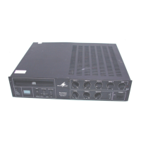
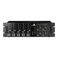
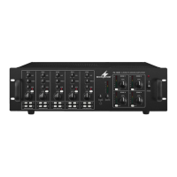
4 Setting up the Amplifier
The amplifier is designed for installation into a
rack (482 mm /19”), but it can also be placed
on a table. Do not block the air vents; air must
be able to flow through the air vents to ensure
sufficient cooling of the power amplifier.
4.1 Installation into a rack
For installation into a rack, screw the two
mounting brackets provided to the sides of the
unit. In the rack, the amplifier requires a height
of 2 RS (1 RS = rack space = 44.45 mm).
To prevent the rack from becoming top-
heavy, insert the amplifier into the lower section
of the rack. The mounting brackets alone are
not sufficient for fixing it safely; additionally use
lateral rails or a bottom plate to secure the unit.
5 Connecting the PA Amplifier
Connections should only be made by experts. Al
-
ways switch off the amplifier before connecting!
5.1 Speakers
Connect either 100 V speakers (fig. 1) and 70 V
speakers (fig. 2) or speakers/speaker groups with
a total impedance of at least 4 Ω (figs. 3 – 5),
refer to page 2. Depending on the speaker type,
use the corresponding contacts of the terminal
strip SPEAKER OUTPUT (13). To make handling
easier, the terminal strip can be removed from
its connector.
When connecting, observe the correct
individual or total impedance of the speakers
and their correct polarity (positive and negative
connections as shown in figs. 1 – 5). The positive
connection of the speakers is always specially
marked.
Caution! In case of PA speakers with a 70 V
or 100 V audio transformer (figs. 1 and 2), the
total load by the speakers must not exceed
120 W; otherwise, the amplifier will be over-
loaded and may be damaged.
5.2 Microphones
Up to three microphones can be connected to
the inputs INPUT 1 to INPUT 3 (14). Instead of
the XLR jack INPUT 1, the screw terminals (20)
can be used alternatively.
1) When connecting a microphone, disengage
the corresponding switch MIC/LINE (19).
2) For the jacks to which a phantom-powered
microphone has been connected, use the cor-
responding DIP switch PHANTOM POWER
(22) to activate the 20 V phantom power
(switch in lower position).
Caution! When the phantom power has
been activated, make sure that no micro-
phone or audio unit with unbalanced output
signal has been connected to the input; it
may be damaged.
5.3 Units with line output
Up to four units with line level output (e. g. CD
player, mixer) can be connected to the inputs
INPUT1 to INPUT 3 (14) and to the input AUXIN
(17). When connecting any units to the inputs
INPUT1 to INPUT 3, engage the corresponding
switch MIC / LINE (19).
5.4 Inserting an equalizer or
anotherunit
For external effects on the sound, insert, for
example, an equalizer via the jacks PRE OUT
and AMP IN (15).
1)
Remove the jumper between the connections
PRE OUT and AMP IN: The preamplifier and
the power amplifier will be separated.
2) Connect the input of the unit to the jack PRE
OUT.
3) Connect the output of the unit to the jack
AMP IN.
Note: The amplifier will not deliver any signal if the
unit inserted is not switched on, if it is defective or not
correctly connected.
5.5 Additional amplifier
If the number of the speakers required is higher
than the number admissible for the amplifier, an
additional amplifier will be required (e. g. PA-
900S from MONACOR). Connect the input of
the additional amplifier to the jack LINE OUT
(16). The output level at the jack is independent
of the control MASTER VOLUME (5).
5.6 Power supply and
emergencypower supply
For continued operation of the amplifier in
case of mains failure, connect a 24 V emer-
gency power supply unit (e. g. PA-24ESP from
MONACOR) to the terminal strip DC INPUT (12).
To make handling easier, the terminal strip can
be removed from its connector. Finally connect
the mains cable provided to the mains jack (9)
and then to a mains socket (230 V/ 50 Hz).
Notes:
1. When a 24 V voltage from the emergency power
supply unit is applied to the terminals DC INPUT,
it will not be possible to switch off the amplifier
with the POWER switch (8). In case of mains failure
or when the POWER switch is set to “Off”, the
amplifier will automatically switch to emergency
power supply.
2. During emergency power supply, the amplifier will
deliver less power than during mains supply.
6 Operation
1)
Prior to switching on the amplifier for the first
time, first set the controls INPUT 1 to 3 (1)
and the controls NETWORK (2), AUX (3) and
MASTER VOLUME (5) to the position “0”.
2) Use the POWER switch (8) to switch on the
amplifier: The LED ON (6) will light up.
3) Turn up the control MASTER VOLUME (5) so
that the subsequent settings will be audible.
4)
Set the volume controls INPUT 1 to 3 (1), NET-
WORK (2) and AUX (3) to the desired value.
5) Use the tone controls BASS and TREBLE (4)
to adjust an optimum sound.
6)
Use the control MASTER VOLUME (5) to
adjust the total volume. A row of five LED
indicators (7) will indicate the output level.
Caution: Never set the audio system to a very
high volume. Permanent high volumes may
damage your hearing!
6.1 Talkover function of channel 1
Via channel INPUT 1, announcements can be
made during a music program. For this purpose,
the volume of the other channels will be auto-
matically attenuated by 40 dB. To activate this
function, engage the button AUTOTALK (21).
 Loading...