Reference 13-4 July 2012 pg.7 of 8Copyright 2012 Monster Tower, Inc.
12
14
IMPORTANT - Final Adjustments and Locking
All bolts must be at least hand tight in the next step or the tower may not pivot
the same way each time while making adjustments.
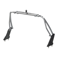
The last steps involve making sure the tower is centered on the boat and locked into place.
This makes the tower sti and silent. IMPORTANT: You must center the tower as shown
to the right. Do this by measuring from the base on one side to the upper pivot bolt on
the other side. Check both diagonal measurements until both measurements are
within 1/4”. When centered, tighten all four pivot bolts on the top section to 22 ft-lbs.
Drilling Holes and Insert Bolts and Nuts to Lock the Tower
Drill holes into each of the 4 Leg Tabs. These holes and the bolts that go through them give
strength and rigidity to the entire tower. Double check that the tower is centered
as above before drilling. Once holes have been drilled, there is no adjusting the tower.
Use the following procedure for drilling holes to make it easier to drill through
the thick tab material.
1) Begin with the included 10mm drill bit. Using the available counter bored hole in
the Top Section as a centering guide for your hole, drill a pilot hole into the tab.
2) Switch the drill bit to a smaller size (3/16” or 1/4“) and drill partially through the tab.
Make sure to stay centered and drill straight into the pilot hole.
3) Switch your drill bit back to the 10 mm and drill to the depth of the smaller hole from step 2.
4) Continue switching between drill bits until you have drilled completely through the tab.
Insert M10 x 40 bolts through each available counter bore hole of the Top Section. Add Nylock Nuts and tighten to 22 ft-lbs..
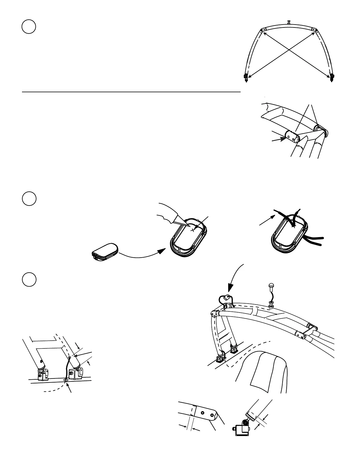
Install the All Round Navigation Light and Run Electrical Wiring
You will need weather tight electrical wire connectors to connect
to your boat electrical system. For forward folding towers you can
conceal the Navigation wiring within the MTK as shown to the right.
For Back folding towers run wire down through the back leg.
Drill a wire out hole near the base of the back Starboard
leg as shown below.
Drill Wire-Out Hole,
1/2” maximum
(back folding only)
NOTE: You may conceal wires for speakers and
other electrical accessories by adding wire in/out
holes. Holes can be up to 1/2”. Avoid solid areas
inside your tower as shown to the right.
1” Solid area
Each Leg
1” Solid area
Top Section
2-3”
Drill Wire-In to Boat, Finish
with Grommet (not included)
Leg Tabs
Available
Counter bored
hole for
centering
All Round
Navigation Light
Wire out through header grommet,
then through Oval Cap from Step 13
then into access window at top of leg
Wire through tow
Wire down
through
front leg
Wire out through
grommet then
into boat
(drill 1/2” maximum wire
hole close to tower base)
Connect to
electrical system
13
Prepare ONE Oval Cap - Oval caps help prevent rain and moisture from entering your MTK.
1. Using a craft knife or blade, cut a small “X” shape
in the underside of ONE black rubber Oval Cap.
Make the “X” as small as possible. You will feed the
Navigation Light wires through it for a nished look.
If you add speakers, do the same for speaker wires.
Oval Cap
(black rubber)
x 1
1. Cut a small “X”
(about 1/4 x 1/4”)
for the Navigation
Light wires.
 Loading...