Exploring the Sample & Hold Circuit | 6
Exploring the
Sample &
Hold Circuit
For a more advanced exercise, let’s
investigate the Sample and Hold
(S+H) section. Unpatch any cables
and match the panel settings to the
initialized patch.
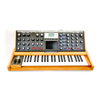
A sample and hold circuit takes two inputs:
an input to be sampled (S+H) and a gate
(S+H GATE). Whenever the GATE input
receives a gate pulse, the voltage in the
S+H input is held at the S+H output until a
new gate comes in.
On Mavis, the S+H input is normalled to
the VCO, meaning that the VCO is already
connected to the S+H input without the
need for a patch cable. If anything else
(say, the EG output) is connected to the
S+H input, the normalled connection is
overridden. Normalled connections are
indicated by parentheses on the Mavis
patch bay: the VCO is normalled to the S+H
(VCO) input and the LFO is normalled to
the S+H GATE (LFO) input.
MAKE THIS CONNECTION
Connect the S+H output to the 1V/OCT
input and press and hold a key down.
You will hear a new pitch in time with the
LFO. If the VCO WAVE knob is rotated to the
square wave you will hear only two pitches
since the square wave being sampled only
oscillates between two voltages. If the VCO
WAVE knob is turned to sawtooth you will
hear random voltages, as the sawtooth wave
sweeps continuously between +5 and -5
volts and (typically) at a rate much faster
than the LFO.
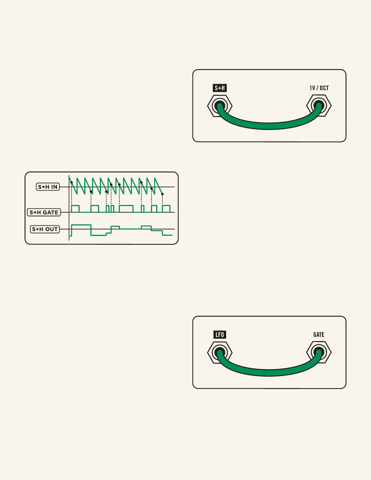
MAKE THIS CONNECTION
Rather than having to press a key, we can
instead use the LFO to trigger a new note
each time the S+H circuit is triggered by
connecting the LFO to the GATE.
Now the LFO is connected to the GATE
triggering a new note with each LFO pulse via
a patch cable, and the LFO is also connected
to the S+H GATE through normalization.

 Loading...