MooNEY
@/-
OWNERS
MANUAL
grip of the pilot's control wheel will de-energize the
P.C.
system while using normal spin recovery techniques. Spin
recovery can be executed from the co-pilot's side by over-
powering the
P,C.
system.
TRIM
CONTROLS
I
For pitch trim control, the entire empennage pivots on the
tailcone attachment points
to
increase or dehease the hori-
zontal stabilizer angle of attack, This design allows flight
trim establishment with minimum control surface deflection.
A pointer in
a
slot located on the aft end of the nose wheel
well indicates stabilizer trim position. Forward rotation
of the trim wheel lowers the nose; rearward rotation raises
the nose in flight.
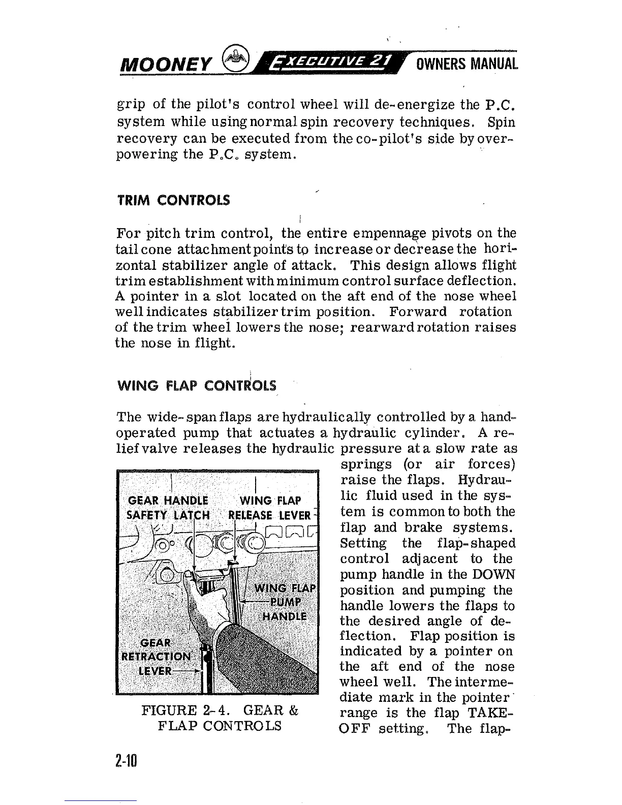
The wide- span flaps are hydraulically controlled by
a
hand-
operated pump that actuates a hydraulic cylinder. A re-
liefvalve releases the hydraulic pressure
at
a
slow rate as
springs (or air forces)
raise the flaps. Hydrau-
lic fluid used in the sys-
tem
is
common to both the
flap and brake systems.
Setting the flap- shaped
control adjacent to the
pump handle in the
DOWN
position and pumping the
handle lowers the flaps to
the desired angle of de-
flection. Flap position
is
indicated by
a
pointer on
the aft end of the nose
wheel well. The interme-
diate mark in the pointer
'
FIGURE
2- 4.
GEAR
&
range
is
the flap TAKE-
FLAP
CONTROLS
OFF
setting. The flap-
 Loading...