EasyManua.ls Logo

Mooney M20M - Page 154

Mooney M20M
399 pages
Print Icon
To Next Page IconTo Next Page
To Previous Page IconTo Previous Page
Loading...
SERVICE
AND
MAINTENANCE
MANUAL
M20M
MOONEY
AIRCRAFT
CORPORATION
8.
Disconnect
nose
gear
doors,
outboard
main
gear
approximately
1.56
inches
*kX
from
forward
face
of
doors,
and
inboard
door
links.
On
outboard
main
gear
truss
at
F.S.
33
(Fig.32-12,
Detail
A).
doors,
disconnect
springs.
On
inboarddoor
bellcranks,
NOTE
disconnect
springs.
Loosen
jamb
nut
(X)
on
retraction
tube
01)
(Fig.
32-11)
and
back
off
pressure
on
spring
This
dimension
m
may
vary
to
permit
connection
of
retraction
tubes
with
zero
(W)
by
loosening
nut
C~.
Disconnect
retraction
tube
O~
from
bellcrank
(C)
(Fig.
32-3).
preload
at
bolt
hole.
9.
Position
main
retraction
bellcrank
(A)
so
center
of
10´•
With
main
retract
bellcrank
held
in
position,
turn
forward
hole
in
the
left
outboard
arm
of
bellcrank
is
actuator
barrel
nut
until
rod
end
bearing
aligns
with
in
bellcrank;
install
connection
bolt
at
(N),
Fig.
-12.
11.
Position
bellcrank
(C)
(Fig.
32-3),
so
center
of
pin
(D)
on
top
leg
is
1.35
inches
from
bottom
of
spar
cap
(E).
This
will
be
the
starting
position
landing
gear
is
in
down
and
locked
over
center,
O
~L
~Vith
cut
any
preload
set.
12.
Adjust
retraction
tube
(V)
(Fig.
32-11),
at
rod
until
it
will
connect
to
bellcrank
(C)
(Fig.
32-3)
with
connection
bolt/hardware,
leaveat
this
time.
13.
Adjust
rod
end
on
retraction
tube
(L)
(Fig.
32-7)
attach
hole
is
aligned
with
inboard
bellcrank
at
(M).
connection
bolt/hardware.
14.
Disconnect
retraction
tube
(V)
at
bellcrank
(C)
end;
position
disconnected
gear
full
down
and
over
center.
Both
LH
and
RH
landing
gear
be
in
this
configuration
at
this
time.
15.
PUSH
landing
gear
actuator
C/B
IN.
16.
Turn
MASTER
Switch
ON.
17.
Extend
main
gear
actuator
to
fully
extended
Make
certain
lugs
on
main
retract
bell
crank
not
contact
fuselage
tubes,
floorboard
or
actuator
nut.
If
there
is
any
contact,
run
actuator
back
up
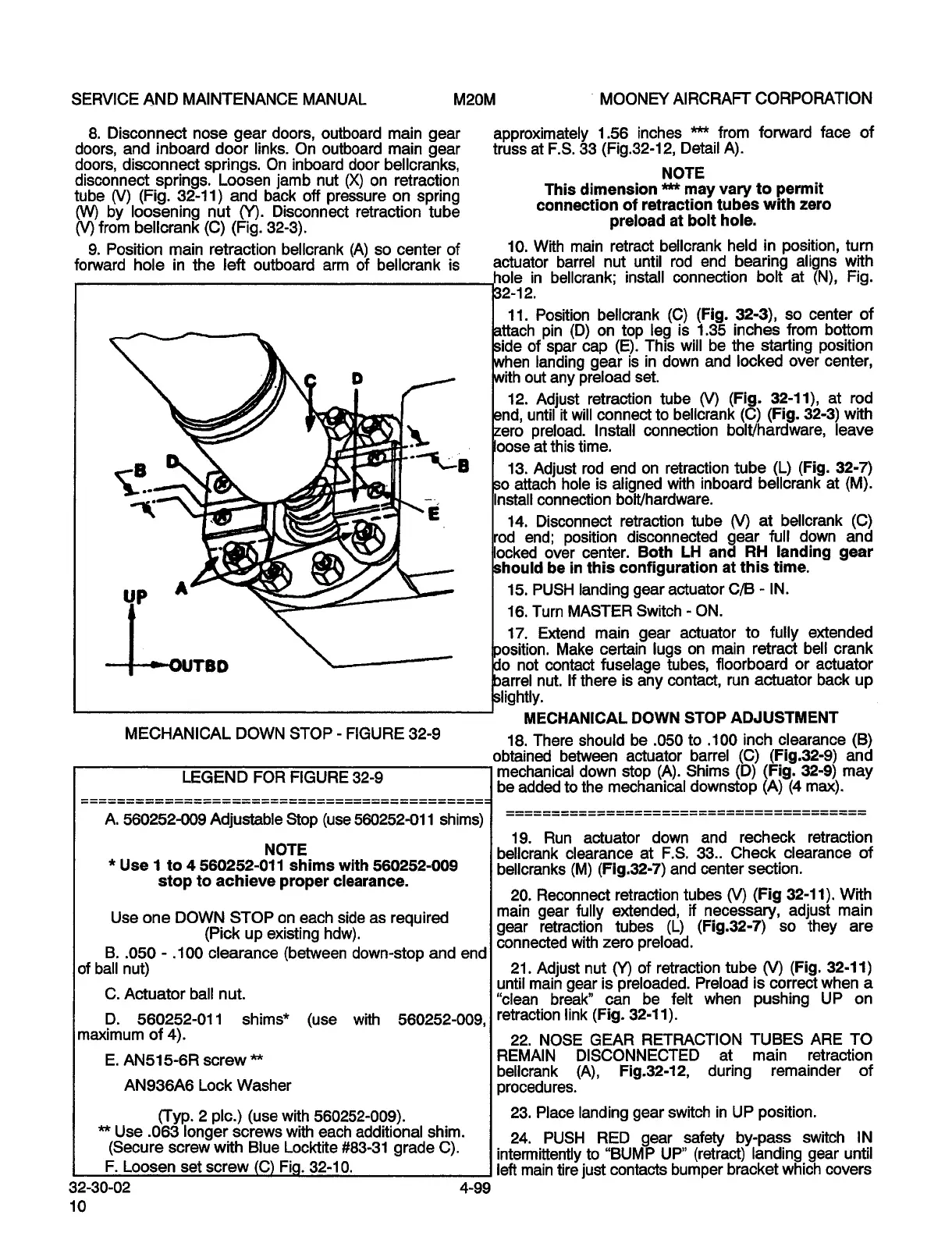
MECHANICAL
DOWN
STOP
ADJUSTMENT
MECHANICAL
DOWN
STOP
FIGURE
32-9
18.
There
should
be
.050
to
.100
inch
clearance
(B)
obtained
between
actuator
barrel
(C)
(Fig.32-9)
and
LEGEND
FOR
FIGURE
32-9
mechanical
down
stop
(A).
Shims
(D)
(Fig.
32-9)
may
be
added
to
the
mechanical
downstop
(A)
(4
max).
A.
560252-009
Adjustable
Stop
(use
560252-011
shims)
19.
Run
actuator
down
and
recheck
retraction
NOTE
bellcrank
clearance
at
F.S.
33..
Check
clearance
of
Use
1
to
4
560252-011
shims
with
560252-009
bellcranks
(M)
(Fig.32-7)
and
center
section.
stop
to
achieve
proper
clearance.
20.
Reconnect
retraction
tubes
O~
(Fig
32-11).
With
Use
one
DOWN
STOP
on
each
side
as
required
main
gear
fully
extended,
if
necessary,
adjust
main
(Pick
up
existing
hdw).
gear
retraction
tubes
(L)
(Fig.32-7)
so
they
are
connected
with
zero
preload.
B..050
.100
clearance
(between
down-stop
and
end
of
ball
nut)
21.
Adjust
nut
(Y)
of
retraction
tube
(V)
(Fig.
32-11)
until
main
gear
is
preloaded.
Preioad
is
correct
when
a
C.
Actuator
ball
nut.
"clean
break"
can
be
felt
when
pushing
UP
on
D.
560252-011
shims*
(use
with
560252-009,
i
’et’action
link
(Fig.
32-11).
maximum
of
4).
22.
NOSE
GEAR
RETRACTION
TUBES
ARE
TO
E.
AN515-6R
screw
M
REMAIN
DISCONNECTED
at
main
retraction
bellcrank
(A),
Fig.32-12,
during
remainder
of
AN936A6
Lock
Washer
procedures.
(Typ.
2
pie.)
(use
with
560252-009).
23.
Place
landing
gear
switch
in
UP
position.
Use
.063
longer
screws
with
each
additional
shim.
24.
PUSH
RED
gear
safety
by-pass
switch
IN
(Secure
screw
with
Blue
LocMite
#83-31
grade
C).
intermittently
to
"BUMP
UP"
(retract)
landing
gear
until
F.
Loosen
set
screw
32-10.
left
main
tire
just
contacts
bumper
bracket
which
covers
3230-02
4-99
10
OLDWILLWAYNE

Table of Contents