EasyManua.ls Logo

Mooney M20M - Cowl Flap Indicator Adjustment

Mooney M20M
399 pages
Print Icon
To Next Page IconTo Next Page
To Previous Page IconTo Previous Page
Loading...
MOONEY
AIRCRAFT
CORPORATION
M20M
SERVICE
AND
MAINTENANCE
MANUAL
1.
With
the
cowi
flaps
open,
adjust
linkage
rods
irom
idler
shaft
arm
of
each
cowl
flap
to
their
maximum
length.2.
Close
cowl
flaps
and
measure
the
distance
PIN
K81
R8
I
between
the
cowl
flap’s
trailing
edges
and
fuselage
z
lower
forward
skin
line.
PIN
F
3.
Open
cowl
flaps
and
readjust
the
linkage
rod,
r,
O
o
decreasing
the
length
by
the
measured
amount.
t
o
4.
Close
cowl
flaps
and
ensure
that
cowl
flaps
are
not
outside
the
fusdage
contour
nor
that
the
cowl
flaps
are
preloaded.
Readjust
as
required.
71-13-01
-COWL
FLAP
INDICATOR
ADJUSTMENT
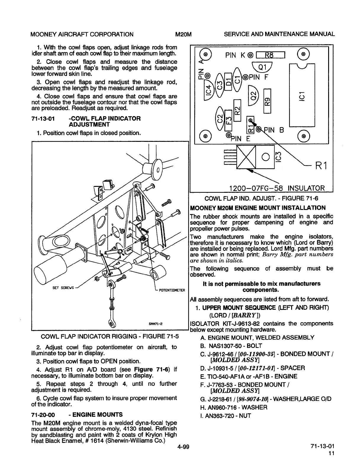
1.
Position
cowl
Raps
in
closed
position.
IN
B
0
13
R1
1200-07FG-58
INSULATOR
COWL
FLAP
IND.
ADJUST.
FIGURE
71-6
MOONEY
M20M
ENGINE
MOUNT
INSTALLATION
The
rubber
shock
mounts
are
installed
in
a
specific
01,
sequence
for
proper
dampening
of
engine
and
propeller
power
pulses.
Two
manufacturers
make
the
engine
isolators,
it
is
necessary
to
know
which
(Lord
or
Barry)
are
installed
or
being
replaced.
Lord
Mfg.
part
numbers
are
shown
in
normal
print;
Barry
Mfg.
part
rtumbers
are
8hown
in
italics.
The
following
sequence
of
assembly
must
be
observed.
It
is
not
permissable
to
mix
manufacturers
SET
SCREWS
~W
POTENTIOIIETER
components.
All
assembly
sequences
are
listed
from
aft
to
forward.
1.
UPPER
MOUNT
SEQUENCE
(LEFT
AND
RIGHT)
(LORD
I[BARRYI)
snwl-e
ISOLATOR
KIT-J-9613-82
contains
the
components
below
except
mounting
hardware.
COWL
FLAP
INDICATOR
RIGGING
FIGURE
71-5
A.
ENGINE
MOUNT,
WELDED
ASSEMBLY
2.
Adjust
cowl
flap
potentiometer
on
aircraft,
to
B.
NAS1307-50-BOLT
illuminate
top
bar
in
display.
C.
J-ss12-46
[00-11900-35]
BONDED
MOUNT
i
3.
Position
cowl
flaps
to
OPEN
position.
[IMOLDED
ASSY]
4.
Adjust
R1
on
A/D
board
(see
Figure
71-6)
if
D.
J-10931-5/
[00-12171-01]-
SPACER
necessary,
to
illuminate
bottom
bar
on
display.
E.
TIO-540-AF1A
or
-AF1B
ENGINE
5.
Repeat
steps
2
through
4,
until
no
further
F.
J-7763-53
BONDED
MOUNT
I
adjustment
is
required.
[MOLDED
ASSY]
6.
Cycle
cowl
flap
system
to
insure
proper
movement
G.
J-221&61
1
[98-907~CI0]
WASHER,LARGE
O/D
of
the
indicator.
H.
AN960-716-
WASHER
71-20-00
ENGINE
MOUNTS
I.
AN363-720-
NUT
The
M20M
engine
mount
is
a
welded
dyna-focal
type
mount
assembly
of
chrome-moly,
4130
steel.
Refinish
by
sandblasting
and
paint
with
2
coats
of
Krylon
High
Heat
Black
Enamel,
1614
(Sherwin-Wiiliams
Co.)
4-99
71-13-01
OLDWILLWAYNE

Table of Contents