EasyManua.ls Logo

Mooney M20M - Page 26

Mooney M20M
399 pages
Print Icon
To Next Page IconTo Next Page
To Previous Page IconTo Previous Page
Loading...
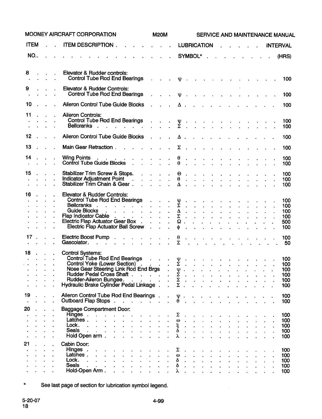
MOONEY
AIRCRAFT
CORPORATION
M20M
SERVICE
AND
MAINTENANCE
MANUAL
ITEM
ITEM
DESCRIPTION
LUBRICATION
INTERVAL
NO..
SYMBOL"
(HRS)
8
Elevator
Rudder
controls:
Control
Tube
Rod
End
Bearings
100
9
Elevator
Rudder
Controls:
Control
Tube
Rod
End
Bearings
’LCI
100
10
Aileron
Control
Tube
Guide
Blocks
100
11
Aileron
Controls:
Control
Tube
Rod
End
Bearings
100
Bellcranks
C
100
12
Aileron
Control
Tube
Guide
Blocks
100
13
Main
Gear
Retraction
Z
100
14
Wing
Points
8
100
Control
Tube
duide
Blbcks
8
100
15
Stabilizer
Trim
Screw
Stops.
0
100
Indicator
Adjustment
Point
8
100
Stabilizer
Trim
Chain
Gear
100
16
Elevator
Rudder
Controls:
Control
Tube
Rod
End
Bearings
100
Bellcranks
Z
100
Guide
Blocks
B
100
FlaplndicatorCable
Z
100
Electric
FlapActuatorGearBox
SZ
500
Electric
Flap
Actuator
Ball
Screw
100
17
ElectricBoost
Pump
8
100
Gascolator.
Z
50
18
Control
Systems:
Control
Tube
Rod
End
Bearings
’IC~
100
Control
Yoke
(Lower
Section)
100
Nose
Gear
Steering
Link
Rod
End
Brgs
100
Rudder
Pedal
Cross
Shaft
I:
100
Rudder-Aileron
Bunwee.
Z
100
Hydraulic
Brake
Cylind~er
Pedal
Linkage
X
100
19
Aileron
Control
Tube
Rod
End
Bearings
100
Outboard
Flap
Stops
8
100
20
Baggage
Compartment
Door:
Hinges
Z
100
Latches
o.
100
Lock.
100
Seals
6
100
Hold
Open
arm
h
100
21
Cabin
Door:
Hinges
Z
100
Latches
w.
100
Lock.
6
100
Seals
6
100
Hold-Open
Arm
h
100
See
last
page
of
section
for
lubrication
symbol
legend.
5-20-07
4-99
18
OLDWILLWAYNE

Table of Contents