- 13 -
’
MSSTAC6 Step Motor Drive User Manual
MOONS’
www.moons.com.cn
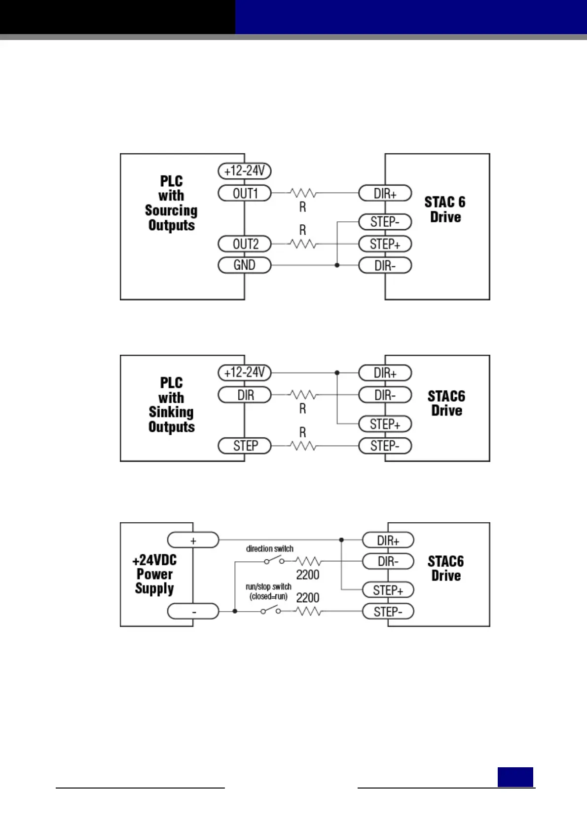
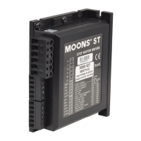
• For 12 volt logic, add 820 ohm, 1/4 watt resistors
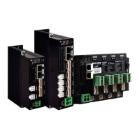
• For 24 volt logic, use 2200 ohm, 1/4 watt resistors
WARNING: The maximum voltage that can be applied directly to a high speed input terminal
is 5 volts. Never apply high voltage AC to an input terminal.
Connecting to PLC with Sourcing (PNP) Outputs
(Most PLCs use 24 volt logic)
Connecting to PLC with Sinking (NPN) Outputs
(Most PLCs use 24 volt logic)
Using Mechanical Switches at 24 volts
Standard Digital Inputs
As mentioned above, the STEP and DIR inputs are configured for 5 volt logic. All other digital inputs are
designed for operation between 12 and 24VDC.
This includes five inputs on the main board and the eight
digital inputs on the expanded I/O board (IN/OUT2).
Single Ended Inputs