TECHNICAL SPECIFICATIONS – FOLDING WHEELCHAIRS | USER MANUAL
NOTE: If you ignore these warnings or fail to inspect or maintain your wheelchair as directed in the manual, you may fall, tip over or lose control of the wheelchair and seriously injure yourself or others and damage the
wheelchair.
16
– Press downwards on both seat rails in order to engage the lock
mechanism of the wheelchair. Sometimes, it is necessary to
press on the back of the seat to make sure that they are cor-
rectly positioned in the seat rail supports. You will feel a click
between frame components.
– If the chair has a rigid seat pan option, reinstall it.
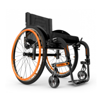
7.2 WHEEL LOCKS
WARNINGS
Never use wheel locks to slow or stop wheelchair movement.
WHEEL LOCKS ARE NOT BRAKES.
Make sure the surface is not slippery as the wheelchair could
move even though the wheel locks are engaged.
Make sure the stem locks embed at least 3 mm when they
are engaged. The tire must be inflated properly.
Make sure the wheelchair is stable and fully locked before
wheel locks are engaged.
– To engage the locks, push the wheel lock handle forward (for
push-to-lock type) or pull wheel lock backward (for pull-to-lock
type) until the lock is fully engaged and that the wheelchair is
stable.
– To release the locks, pull the wheel lock handle backward (for
push-to-lock type) or push wheel lock handle forward (for pull-
to-lock type) until the lock is fully released.
INFORMATION
Note that for unilateral wheel lock, the engagement or disen-
gagement of the wheel lock is done on one side only.
7.3 FOOTRESTS
7.3.1 INSTALLING AND REMOVING
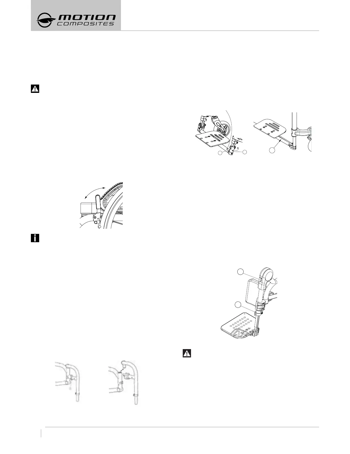
INSTALLATION (EXCLUDING VELOCE)
– Insert the front rigging pivot into the wheelchair’s mounting
tube.
– Then, rotate the front rigging outward the wheelchair and rotate
it forward until the mechanism locks into place.
– Repeat this procedure for the other side.
REMOVING (EXCLUDING VELOCE)
– Push the release locking lever (1) (Fig. a) inward or outward
and maintain that position so that the front riggings can rotate
freely.
– Rotate front riggings outwards or inwards to disengage the
locking mechanism.
– Lift the front riggings up (Fig. b) so as to disconnect it from the
footplate.
– Repeat this procedure for the other side.
Fig. a Fig. b
OPENING AND CLOSING THE FOOTREST WITH FULLWIDTH FLIP
UP OR AUTOFOLDING FOOTPLATE
– The VELOCE may be supplied with an optional flip-up (Fig, c)
or auto-folding footplate (Fig. d). The HELIO C2 may be supplied
with an optional flip-up (Fig, c).
– The single flip-up model can be opened and closed the following
way:
– Rotate the ring (1) to unlock and open the locking mechanism.
– Lift (2) the footplate to open.
– When closing make sure to secure the shaft head in the locking
mechanism.
– Make sure the footplate is secure once closed.
Fig. c Fig. d
– When transferring, avoid putting weight on the footrest and be
careful not to stand behind the footplate.
– Never use footrests to lift the wheelchair.
– Only use non-detachable parts to lift the wheelchair.
7.3.2 ELEVATING LEGREST
7.3.2.1 INSTALLING THE ELEVATING LEGREST
– Remove the current footrest, see section 7.3.1.
– Install the elevating legrest the same way to install a footplate,
see section 7.3.1.
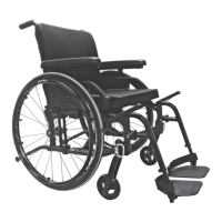
7.3.2.2 ADJUSTING THE ELEVATING LEGREST
– To change the legrest length, pull on the lever (1) to open the
clamp.
– Change the length and push on the lever (1) to close the clamp.
– To change the legrest angle, set the desired angle while push-
ing on the red button (2).
7.4 ARMREST
WARNING
Ensure that armrests are securely locked into armrest sock-
ets before using it.
– Never lift the wheelchair by holding the armrests.
– Only use non-detachable parts to lift the wheelchair.
7.4.1 FLIP BACK “U” ARMRESTS
TO LIFT THE ARMRESTS:
– Activate the locking lever (1) to release the system.
– Then, lift the armrest and rotate it backwards.
1
2
1
2
1