ADJUSTMENTS AND MAINTENANCE – FOLDING WHEELCHAIRS | USER MANUAL
NOTE: If you ignore these warnings or fail to inspect or maintain your wheelchair as directed in the manual, you may fall, tip over or lose control of the wheelchair and seriously injure yourself or others and damage the
wheelchair.
20
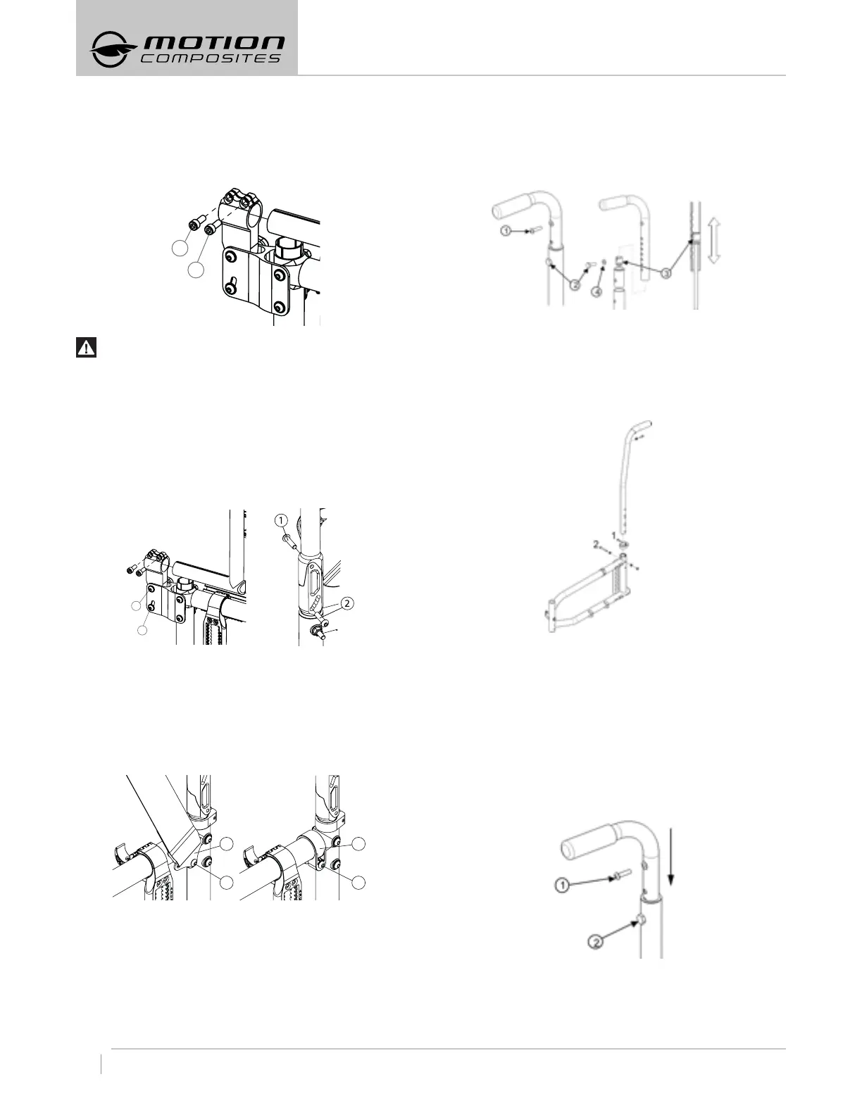
8.5.2 DEPTH ADJUSTABLE OPTION
– Remove bolts (1 and 2).
– Slide the back post forward to remove it from the tube.
– Reinstall the back post in the reverse order while making sure
they are positioned on the right side.
– Tighten bolts (1 and 2) firmly.
WARNING
Weight Limit: 175 lb (79 kg) and not AINSI/RESNA : WC19
compatible.
8.5.3 ADJUSTING THE BACK ANGLE
– Loosen screw (1) and remove screw (2) from the leveling device
(see Fig. a or b depending on the chair’s model).
– Adjust to desired angle using the graduated scale at the lower
part of the leveling device.
– Reinstall screw (2) and tighten both screws
of the device.
– Adjustments: 5° increments from 85° to 110°.
Fig. a Fig. b
8.5.4 REMOVING/INSTALLING THE POSITIONING BELT
– Remove screw (1) in order to remove the positioning belt clamp
(2). (Fig. a)
– Reinstall screw (1) directly on the frame clamp (3) (Fig. b).
– Tighten screw (1) firmly.
– Repeat the same steps on the other side.
1
2
1
3
Fig. a Fig. b
8.5.5 ADJUSTING THE BACKREST HEIGHT
– Remove the screw (1) that holds the back upholstery.
– Pull backrest upholstery down several centimeters in order to
access screw (2) that holds the push handle.
– Remove screw (2) and the backrest handle.
– To adjust the backrest height, move the dowel nut (3), located
inside the handle, using a threaded rod (¼ in.-20).
– Once the dowel nut (3) fits in, use screw (2) to prevent the dowel
nut (3) to move when removing the threaded rod.
– Remove screw (2) and reinstall the backrest handle.
– Align screw (2) with the mounting hole.
– Reinstall and tighten screw (2) and the washer (4).
– Repeat the same steps on the other side.
– Reinstall the backrest upholstery with the screw (1) and tighten
to fit snugly.
8.5.6 ADJUSTING THE 8DEGREE BACKREST HEIGHT
– The 8-degree backrest can be adjusted by removing the bolt (2)
on each side of the frame and by moving the back canes
up or down to the desired height.
– Handles and back upholstery will be adjusted accordingly.
– Adjustable angle back canes should not be moved.
– The back upholstery cannot be adjusted on this model.
8.5.7 REMOVING/INSTALLING
STANDARD BACK UPHOLSTERY
– Remove the screws (1) that hold the back upholstery.
– Pull backrest upholstery down several centimeters in order to
access screw (2) that holds the push handle.
– Remove screw (2) and then remove the backrest handle.
– Remove or install back upholstery.
– Once the new back upholstery is installed, reinstall the handles
by aligning them with the mounting holes.
– Reinstall and tighten screw (2) firmly.
– Install back upholstery at the adequate position and fix it firmly
with screws (1) on each back cane.
8.5.8 REMOVING/INSTALLING BACK UPHOLSTERY
(INTEGRATED PUSH HANDLE)
– Remove screw that holds the back upholstery.
– Remove the 2 bolts on each side of the frame and remove the
back canes.
1
2
1
2