EN
24
The CE24CNC control unit is the most modern, ecient system for
the control of Motorisation Plus motors for the electric opening and
closure of sliding gates. All other, improper, use of the control unit
is forbidden.
The CE24CNC has a display allowing easy programming and
constant monitoring of the input status; the menu structure also
allows easy setting of working times and operating modes.
2.3 - Description of the control unit
2.4 - Description of the connections
1. Motor power supply connections and encoder
2. Transformer power supply connections
3. 24Vdc and 24Vac output connections to controls and safety
devices
4. Connector for battery charger BAT364
5. Limit switch connector
6. Functions display
7. Safety device dip switch
8. Fuse 2A slow-acting
9. STOP-PH2-PH1-OPEN-CLOSE-PAR-SBS safety led and led
input led
10. Limit switch indicator LED LSC
11. Limit switch indicator LED LSO
12. STEPPING SBS button
13. UP + button
14. MENU button
15. DOWN - button
16. Antenna
17. Led
2 - INTRODUCING THE PRODUCT
The use of gear motors for applications which dier from those
indicated above is prohibited.
The gear motor SLIDER is intended to be installed within systems
for the automation of sliding gates. The SLIDER gear motors have
been designed to automate sliding gates within the weight limits
indicated in the technical specications table.
2.1 - Description of the product
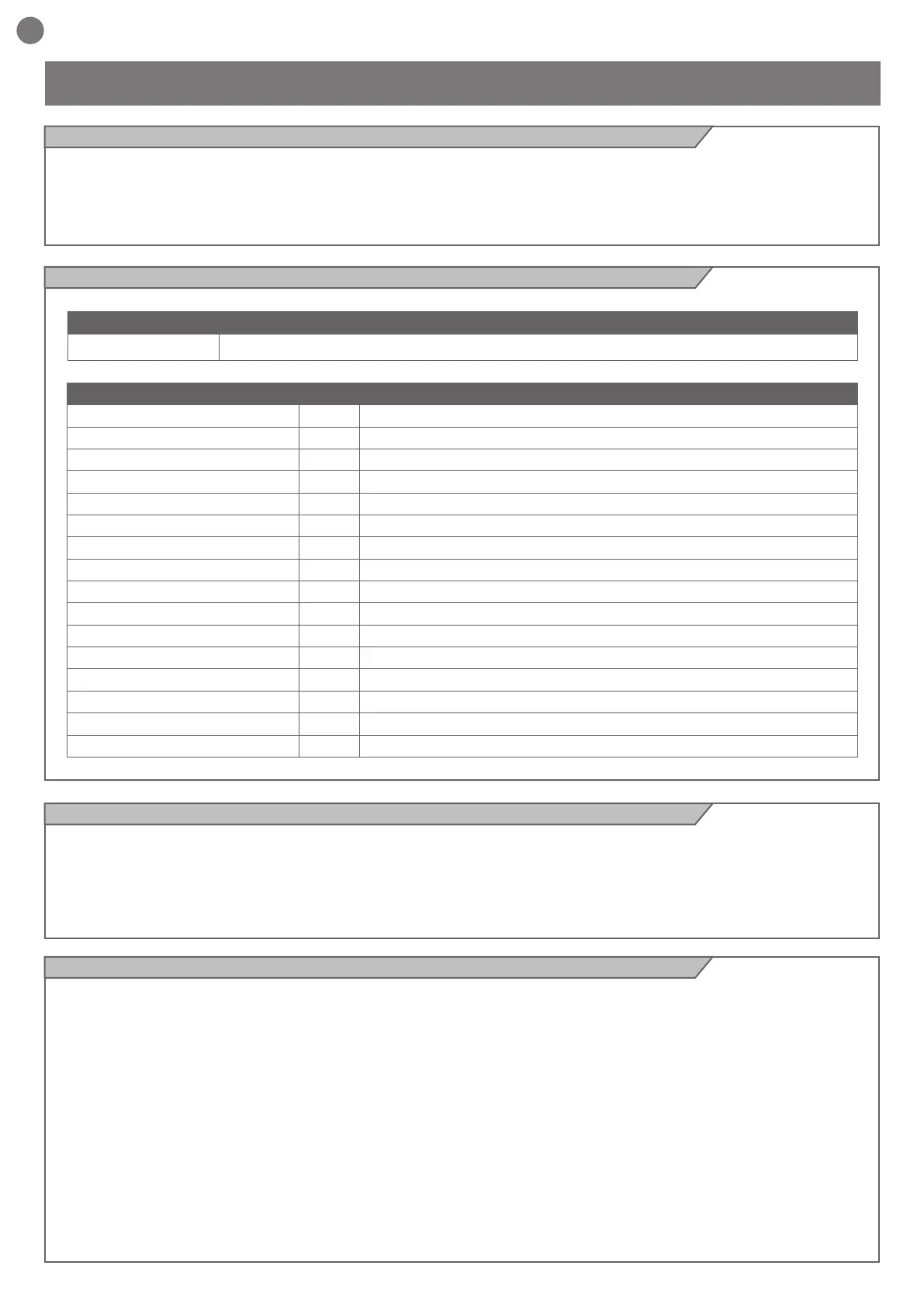
Code Description
SPRINT400 24 Vdc gear motor with mechanical limit switches, gate maximum weight 400 kg
TECHNICAL DATA
MODEL SPRINT400
Speed* cm/s 21
Torque Nm 12
Working cycle % 50
Control unit CE24CNC
Power Vac (Vdc) 230 (24)
Motor consumption A 1,1
Consumption power W 250
Capacitor
µF -
Thermoprotection °C -
Protection degree IP 44
Dimension (L - P- H) mm 320 - 184 - 260
Weight Kg 11
Working temperature
°C -20 +55
Max gate weight Kg 400
Sound emission level dB(A) ≤ 70
2.2 - Model and technical characteristics of the motor