EN
26
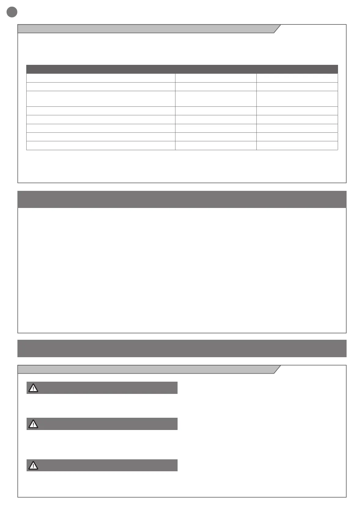
2.6 - List of cables required
Before installing this product, verify and check the following steps:
- Check that the gate or door are suitable for automation
- The weight and size of the gate or door must be within the maximum
permissible operating limits
- Check the presence and strength of the security mechanical stops
of the gate or door
- Check that the mounting area of the product is not subject to
ooding
- Conditions of high acidity or salinity or proximity to heat sources
could cause malfunction of the product
- Extreme weather conditions (for example the presence of snow,
ice, high temperature range, high temperatures) may increase the
friction and therefore the force required for the handling and initial
starting point may be higher than under normal conditions.
- Check that the manual operation of gate or door is smooth and
friction-free and there is no risk of derailment of the same
- Check that the gate or door are in equilibrium and stationary if left
in any position
- Check that the power line to supply the product is equipped with
proper grounding safety and protected by a magnetothermal and
dierential security device
- Provide the power system with a disconnecting device with a gap
of contacts enabling full disconnection under the conditions dictated
by the overvoltage category III.
- Ensure that all materials used for the installation comply with
current regulations
3 - PRELIMINARY CHECKS
ELECTRIC CABLE TECHNICAL SPECIFICATIONS
CONNECTION CABLE MAXIMUM ALLOWABLE LIMIT
Control unit power supply line 1 x câble 3 x 1,5 mm² 20 m *
Flashing light, courtesy light
Antenna
3 x 0,5 mm ² **
1 x câble type RG58
20 m
20 m (conseillé < 5 m)
Electric lock 1 x câble 2 x 1 mm² 10 m
Transmitter photocells 1 x câble 2 x 0,5 mm² 20 m
Receiver photocells 1 x câble 4 x 0,5 mm² 20 m
Sensitive edge 1 x câble 2 x 0,5 mm² 20 m
Key-switch 1 x câble 4 x 0,5 mm² ** 20 m
* If the power supply cable is more than 20 m long, it must be of
larger gauge (3x2.5mm2) and a safety grounding system must be
installed
near the automation unit
** Two cables of 2 x 0.5 mm2 can be used as an alternative
The cables required for connection of the various devices in a
standard system are listed in the cables list table.
The cables used must be suitable for the type of installation; for
example, an H03VV-F type cable is recommended for indoor
applications, while H07RN-F is suitable for outdoor applications.
4 - PRODUCT INSTALLATION
ATTENTION !
The installer must verify that the working temperature range
stated on the automation device is suitable for the location
where it is installed.
ATTENTION !
The automation system must be equipped with a pressure-
sensitive edge protecting all possible crushing points (han-
ds, feet, etc.) in accordance with the requirements of the EN
13241-1 standard.
ATTENTION !
The gate has to be equipped with stop locks at the opening
and closing, which prevent the gate derailment.
Respecting the overall size, x to ground the base-plate through
4 sturdy screw-anchors (g.3) or drown it into the concrete (g.3).
Plan for one or more sheathing for the passage of the power lines.
N.B. The exact dimensions of the rack must be known to allow
precise calculation of the counterplate position.
Fig.2 is an example of a typical system:
Post for photocells (1)
Automation electromechanical (2)
Photocell detectors (3)
Flashing light (4)
Key switch (5)
Radio transmitter (6)
Pressure-sensitive edge (7)
4.1 - Installation