This document provides a comprehensive user and installer's manual for the Motorline Professional OL1500 and OL2000 sliding gate operators, designed for residential and industrial applications.
Function Description
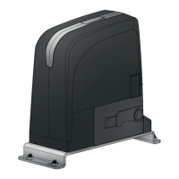
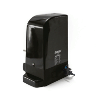
The Motorline Professional OL1500 and OL2000 are automated systems for sliding gates, capable of handling gates with a maximum weight of 1500kg (OL1500) or 2000kg (OL2000). These systems consist of a reversing electro-mechanical gearmotor, powered by a 110V control unit. The integrated programmable electronic control board allows for setting various parameters such as function logics, work time, pause time, anti-crushing sensitivity, and partial-opening width. The reversing system ensures that the gate automatically locks when the motor is not operating, providing enhanced security. A manual release system is also incorporated, allowing the gate to be moved by hand in case of malfunction or emergency. The system is specifically designed for controlling sliding gates and should not be used for any other purpose.
Important Technical Specifications
General Specifications (OL1500 / OL2000):
- Power supply: 110V
- Rated absorbed power: 550W / 1000W
- Max speed: 186mm/snd (for both models)
- Noise: < 56dB (for both models)
- Operating temperature: >-25°C, <65°C (for both models)
- Protection class: IP44 (for both models)
- Thermal protection (°C): 120°C (for both models)
- Leaf max weight (Kg): 1500Kg / 2000Kg
- Working frequency: 70% (for both models)
- Capacitor: 60μF (OL1500) / 25µF and 70μF (OL2000)
Dimensions:
The operator unit has a width of 348.20 mm (313.10 mm at the base), a depth of 430 mm (358 mm at the base), and a height of approximately 165 mm.
System Components (Standard System):
- Motor
- Control board
- Receiver
- Left limit switch plate
- Right limit switch plate
- Rack
- Key selector
- Photocell column
- Safety photocells
- Antenna
- Warning light
- Safety edge
Usage Features
Installation:
The installation process involves several steps:
- Preliminary Checks: Ensure all necessary devices and materials are available, check the operator's Protection Index (IP) and operating temperature suitability, and confirm the gate's perfect function, alignment, and level.
- Foundation Plate Preparation: The foundation plate must be securely fixed to the ground using four supplied nuts and screws, ensuring it is level.
- Operator Positioning: Adjust the distance of the operator from the gate, typically 57mm, as shown in the manual.
- Operator Fixing: Secure the operator by slightly tightening the screws, then screw on the cover. After fixing the upper cover, install the side cover.
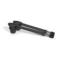
- Releasing the Operator: In case of emergency or malfunction, insert the supplied key into the lock, turn it clockwise 90°, pull, and open the manual release to operate the door manually.
- Rack Installation: Prepare the rack by inserting spacers into all holes. Manually position the gate leaf in the closed position. Bolt the first rack part, supported on the pinion, ensuring it is horizontally leveled. Move the gate back and forth to ensure smooth movement and proper seating of the gear rack on the pinion. Continue setting the rack in the gate, ensuring correct fixation by slowly moving the gate and setting spacers near the pinion.
- Limit Switch Plate Installation: After installing the rack, take the gate back to the closed position. Position the limit switch plate on the rack, ensuring it triggers the limit switch of the motor. Tighten the screws (DIN912 M5X10) included in the kit.
- Clutch Adjustment: The clutch adjustment involves loosening and removing the cover, accessing the adjusting screw, sliding the central box forward, and adjusting the screw in the upper part of the engine using a 6mm umbrella key. Turning clockwise increases the force, while counter-clockwise decreases it. The tuning must achieve a balance between the gate's irreversibility and the engine's power.
Electrical Connections:
- OL1500: Connect the four motor wires (Yellow/Green, Brown, Blue, Black) to the appropriate inputs of the control board. The wires of the permanent capacitor (110Vac) must be connected directly to the control board.
- OL2000: Similar to OL1500, connect the four motor wires to the control board. This motor requires two capacitors: one permanent (25µF, 110Vac) and one for start-up (70µF, 110Vac), connected as per the provided scheme.
- Cable Routing: All electrical cables must be routed through protective tubes to guard against mechanical exertions, especially the power supply cable. All cables must enter the central unit from the bottom. Low voltage connection cables should always be separated from AC110V power cables to avoid interference.
Safety Warnings for Users:
- Read the manual carefully and keep it in a safe place.
- The product is for its intended use only; any other use is prohibited.
- Installation and repair should only be performed by qualified technicians.
- Regularly inspect installations for unbalance and wear.
- Do not use the product if repair or adjustment is needed.
- Disconnect from power supply before maintenance, cleaning, or part replacement.
- Children should not play with the product or opening devices.
- Keep the manual release label permanently attached near the release mechanism.
Safety Warnings for Technicians:
- Ensure all necessary devices and materials are available before installation.
- Provide the manual to the user and explain emergency handling.
- If a pedestrian door is present on the gate, install a door locking mechanism.
- Do not install the product "upside down" or supported by inadequate elements.
- Do not install in explosive environments.
- Install safety devices to protect against crushing, cutting, and other dangers.
- Verify that all elements to be automated are in perfect function and alignment.
- Install the central unit in a safe place, protected from fluids, dust, and pests.
- If the automatism is installed at a height greater than 2.5m, comply with relevant safety and health requirements for work equipment.
Maintenance Features
- Regular Checks: Carry out the following operations at least every 6 months:
- Check the efficiency of the release system.
- Check the efficiency of the safety devices and accessories.
- Repairs: For any repairs, contact the authorized repair centers.
- Cleaning: The use, cleaning, and maintenance of this product may be carried out by persons aged eight years old and over, or by persons with reduced physical, sensorial, or mental capacities, or without knowledge of the product, provided they are supervised and instructed by experienced persons who understand the risks involved.
- Disconnection: When performing maintenance, cleaning, and replacement of parts, the product must be disconnected from the power supply, including any operation that requires opening the product cover.
This product is certified in accordance with European Community (EC) safety standards and complies with Directive 2011/65/EU (RoHS) and Delegated Directive (EU) 2015/863 regarding hazardous substances in electrical and electronic equipment. It also includes markings indicating susceptibility to electric shock and proper disposal guidelines for electronic waste to promote sustainable reuse of material resources.