Introduction
1-7
1
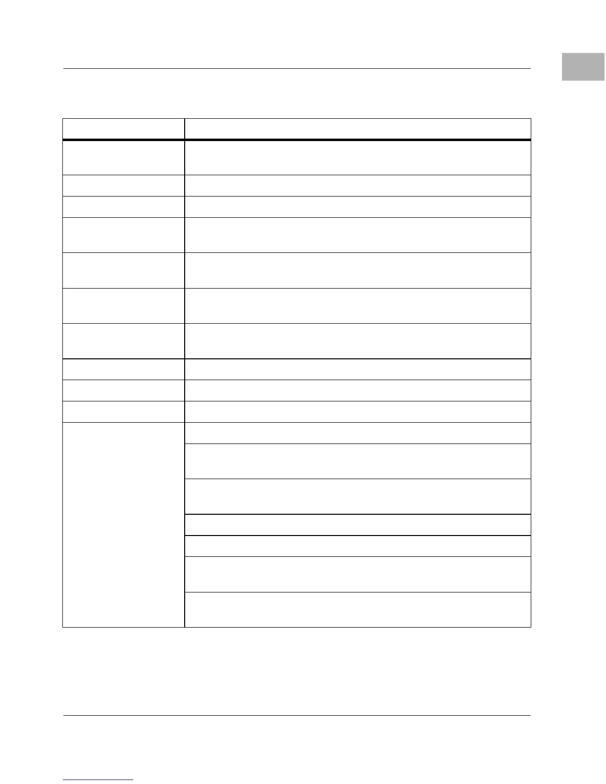
NVRAM 8K by 8 Non-Volatile RAM (NVRAM) and time-of-day
(TOD) clock with battery backup
Switches RESET and ABORT switches
Status LEDs Status LEDs for
FAIL, RUN, SCON, and FUSES
Tick Timers Four 32-bit tick timers (in the MC2chip ASIC); two 32-bit
tick timers (in the VMEchip2 ASIC) for periodic interrupts
Watchdog timers Two 32-bit watchdog timers (one each in the MC2chip and
VMEchip2 ASIC
s)
Interrupts Eight software interrupts (for MVME162LX versions that
have the VMEchip2)
Serial I/O Four serial ports with EIA-232-D interface (serial port
controllers are the Z85230 chips)
SCSI I/O Optional SCSI Bus interface with DMA
Ethernet I/O Optional Ethernet transceiver interface with DMA
IndustryPack I/O Two IP interfaces with two-channel DMA
VMEbus interface
VMEbus system controller functions
VMEbus interface to local bus (A24/A32,
D8/D16/D32/block transfer [D8/D16/D32/D64])
Local-bus-to-VMEbus interface (A16/A24/A32,
D8/D16/D32)
VMEbus interrupter
VMEbus interrupt handler
Global control/status register for interprocessor
communications
DMA for fast local memory - VMEbus transfers
(A16/A24/A32, D16/D32/block transfer)
Table 1-1. 700/800-Series MVME162LX: Features (Continued)
Feature Description

 Loading...


