AP-6511 Access Point Installation Guide
2
• Verify any device connected to this unit is properly wired and grounded.
• Verify there is adequate ventilation around the device, and ambient temperatures meet
equipment operation specifications.
1.3 Site Preparation
• Consult your site survey and network analysis reports to determine specific equipment
placement, power drops etc.
• Assign installation responsibility to the appropriate personnel.
• Identify and document where all installed components are located.
• Ensure adequate, dust-free ventilation to all installed equipment.
• Prepare Ethernet port connections.
• Verify cabling is within the maximum 100 meter allowable length.
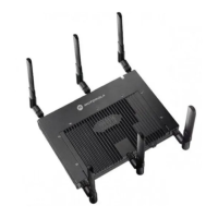
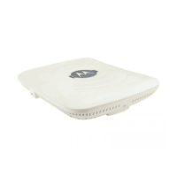
1.4 AP-6511 Package Contents
The AP-6511 model Access Point ships with internal (integrated) antennas.
• AP-6511 Access Point
• Mounting plate (used for both wall mount and Telco Box installations)
• Mounting plate lock screw
• AP-6511 Installation Guide (This Guide)
• RJ-45 double plug interconnect cable
• Fast Ethernet port 1 interconnect cable
1.5 Features
• One RJ-45 PoE Ethernet port (built into the AP-6511 access point)
• Optional second RJ-45 Ethernet port utilizing a pass through (keystone) cable (included)
• Optional three port Ethernet expansion module (sold separately)
• 2 LED indicators
The pass through (keystone) cable provides an option to add a second Ethernet port before installing
the AP-6511.
The AP-6511 has one RJ-45 connector supporting an 10/100 Ethernet port and requires 802.3af
compliant power from an external source.
The AP-6511 ships with a single dual-band radio supporting the 802.11a/b/g/n radio bands.
 Loading...