40 AP 7161 Access Point
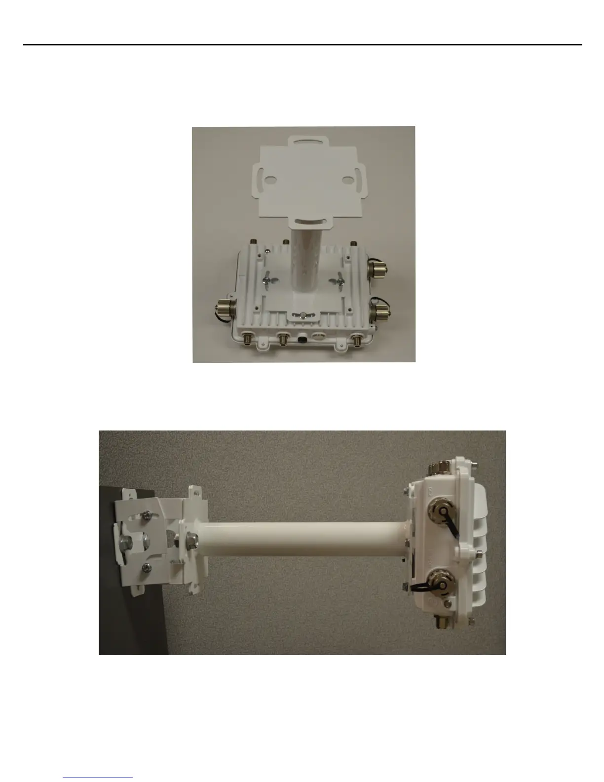
3. With the Access Point positioned so that the gore vent is facing down, attach the extension arm to the
Access Point using four M6 hex flange screws. The two oval holes must be positioned on the short sides
of the Access Point. Tighten the hex flange screws to 60 inch pounds (lbf-in).
4. With the Access Point positioned so that the gore vent is facing down, attach the extension arm to the
Access Point bracket section with two ½ inch bolts and nuts. Tighten bolts to 300 inch pounds (lbf-in).

 Loading...