6881096C77-O September 26, 2003
Introduction: Control Heads 1-3
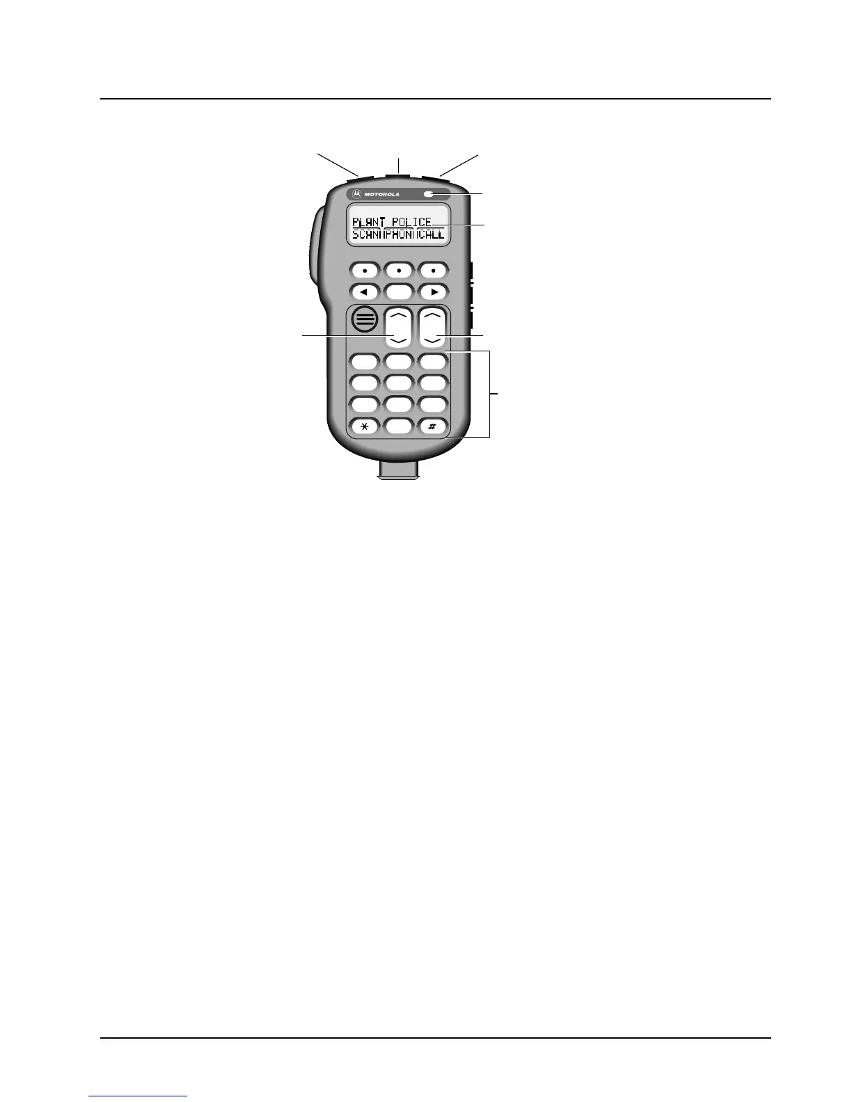
Figure 1-1. Typical W3 Hand-Held Control Head
1.3.1.1 W3 Controls
On/Off Button (T1): Turns the radio on and off. Can be used as an additional programmable button if the
on/off function is not used.
Orange Programmable Button (T2): Programmed at the factory for emergency use. Field
programmable by a qualified radio technician.
Programmable Button (T3): Field programmable by a qualified radio technician.
LED Indicator: Green/red light-emitting diode. Indicates operating status.
Display: 2-line by 14-character display. Provides visual information about many radio features.
Keypad. Provides control of, and data interface with, many features.
Programmable Side Button 1 (S1): Field programmable by a qualified radio technician.
Programmable Side Button 2 (S2): Field programmable by a qualified radio technician.
Programmable Side Button 3 (S3): Field programmable by a qualified radio technician.
Mode Control: Used for selecting modes and programming menus.
Volume Control: Used for selecting volume level, editing names, and making certain radio adjustments.
Push-To-Talk (PTT) Button: Engages the transmitter.
MODE
HOME
2ABC1QZ
3DEF
4GHI
5JKL
6MNO
7PRS
8TUV
9WXY
0
VOL
Side Button 1 (S1)
Side Button 2 (S2)
Side Button 3 (S3)
On/Off
Button
(T1)
Push-To-Talk
(PTT) Switch
LED
Indicator
Alphanumeric
Keypad
Volume
Control
Mode Control
Orange Programmable
Button
(T2)
Programmable
Button
(T3)
Display
Button

 Loading...


