6881096C77-O September 26, 2003
Theory of Operation: W4, W5, and W7 Control Heads 3-7
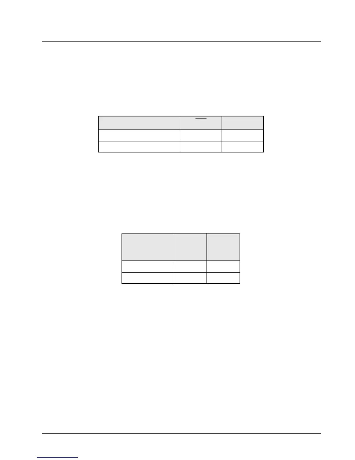
3.2.8 Push-To-Talk (PTT)
The PTT line from the microphone keys the transmitter. This line (U4-37) is normally biased at
5 volts, but goes to DIG GND when the microphone PTT button is pressed. This causes the PTT line
(U1-21) to go high. The transmit command is then sent over the serial bus to the radio command
board. Releasing the PTT reverses this process. There is no PTT hardware connection from the
control head to the radio command board. See
Table 3-4.
3.2.9 Hang-Up Button (HUB)
The control head senses when the microphone is off-hook by monitoring the HUB line from the
microphone. When the microphone is on-hook, the HUB line (U4-31) is connected to ground, placing
a high on the inverted HUB line (U1-20) and sending the on-hook command over the serial bus.
When the microphone is off-hook, U4-31 biases to 5 volts, reversing the process and sending the off-
hook command over the serial bus. See
Table 3-5.
3.2.10 Ignition Sense Circuitry
Ignition sense voltage is sensed by U4-28. When this voltage is high, U4-29 goes low, resulting in
U1-39 going low, and sending the “ignition-on” command over the serial bus. When the ignition
voltage drops off, the process is reversed.
3.2.11 Keypad Scan
U1 scans the keypad switches for a button press by sending out periodic low-going pulses in
sequence on pins 8 through 12. Keypad sense lines connect back to U1 on pins 13 through 17.
Resistors R120 through R124 ensure that the sense lines are high until a key is pressed. When a
button is pressed, keypad contacts close, allowing the low-going pulse to return to the
microcomputer on the appropriate sense line. This informs U1 that a particular button was pressed.
3.2.12 Vacuum Fluorescent (VF) Voltage Converter Circuitry
Voltage for the VF display is generated by a fixed-frequency, variable duty-cycle controlled, flyback
voltage converter. The switching frequency is about 210 kHz. One half of U3, pins 5-7, forms a
210 kHz sawtooth oscillator. The sawtooth waveform is produced at U3-6 and is applied to pin 3 of
the other half of U3. This portion of U3 is a duty-cycle controlled comparator.
Table 3-4. PTT Logic States
Microphone Push-to-Talk PTT PTT
PRESSED Low High
RELEASED High Low
Table 3-5. HUB Logic States
Microphone
Hang-Up
Button
HUB Line
Inverted
HUB
ON-HOOK Low High
OFF-HOOK High Low

 Loading...


