September 26, 2003 6881096C77-O
5-10 Troubleshooting: Replacing the Control-Head Board
5.6.3 W9 Control Heads
NOTE: Before disassembling the W9 control head, note the location of the labeled buttons.
NOTE: Refer to
Figure 7-4, “W9 Pushbutton Control Head Exploded View,” on page 7-5 and
Table 7-5, “W9 Pushbutton Control Head Parts List,” on page 7-5 for the callout numbers in
this section.
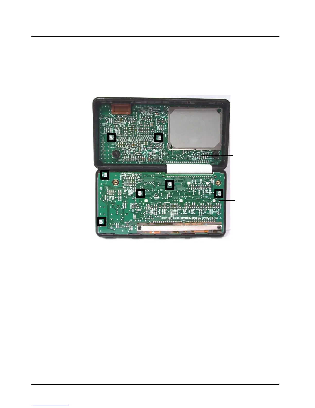
Figure 5-4. W9 Control Head Control Board and Display Board
1. Using a Torx T15 driver, remove the two 30 mm machine screws [29] from the back housing
[31] of the control head.
2. Fold the front housing [41] over so that the front housing is face down and the back housing is
on your working surface with the flex cable [18] attached.
3. Using a Torx T10 driver, remove the five 8 mm self-tapping screws [17] from the Display
Board Kit [37], the two 10 mm captive screws [12] with the leaf assembly spring [11], and the
two 16 mm tapping screws [38] from the control PC board.
4. Remove the Command Board Kit [36] from the back housing and the Display Board Kit [37]
from the front housing.
5. Remove the elastomer keypad [7], ON/OFF switch gasket [34], the “D” Connector Gasket
[33], the solder-side shield [16], and the component-side shield [19] from the PC boards.
Control Board
Display Board
16 mnm self-tapping screws
(2)
8 mnm self-tapping screws
(5)

 Loading...


