Radio Tuning and Programming: Radio-to-Radio Cloning 5-3
5.3.1 Initial Test Equipment Control Settings
The initial test equipment control settings are listed in Table 5-1.
5.4 Radio-to-Radio Cloning
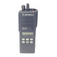
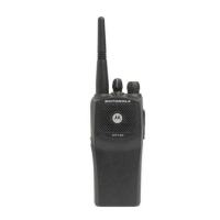
1. Cloning is the process of copying the content of one radio (source radio) into another radio (desti-
nation radio). Radio content refers to system-type features such as frequency, squelch type
options, trunking, etc.
Radio functionality inherent in one radio cannot be cloned to another radio that does not contain the
same functionality. Tuning and alignment information are not transferable and are not affected by
cloning.
1. Signaling Identification Numbers (IDs) are duplicated in the cloning process. Unique IDs may be
assigned with the CPS.
Table 5-1. Initial Equipment Control Settings
Service Monitor Test Set Power Supply
Monitor Mode: Power Monitor Speaker set: A Voltage: 13.2 Vdc
RF Attenuation: -70 Speaker/load:
Speaker
DC on/standby:
Standby
AM, CW, FM: FM PTT: OFF Volt Range: 20 V
Oscilloscope Source: Mod
Oscilloscope Horizontal: 10 mSec/Div
Oscilloscope Vertical: 2.5 kHz/Div
Oscilloscope Trigger: Auto
Monitor Image: Hi
Monitor BW: Nar
Monitor Squelch: mid CW
Monitor Volume: 1/4 CW
Current: 20 A
Note:
The source radio’s serial number cannot be blank.
Note:
Unsuccessful cloning attempts generates a continuous tone and may be an
indication that the destination radio’s codeplug is corrupted.
 Loading...
