6 Getting Started (cont.)
5 Getting Started (cont.)
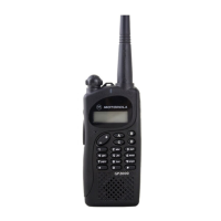
Figure 1.
Controls, Switches,
Indicators, and
Connectors
JT 1000
4 three-position
(ABC) toggle switch
5 indicator LED
6 orange top button
2 channel selector
1 on/off/volume control
13 universal
connector
7 side button 1
8 side button 2
9 side button 3
10 push-to-talk
(PTT) switch
12 microphone
14 noise-
cancelling
port
A
B
C
11 display
3 two-position concentric switch
1
3
5
7
13
15
9
11
HOME
2
ABC
1
3
DEF
6
MNO
5
JKL
4
GHI
7
PRS
8
TUV
9
WXY
0
15 keypad
Feature
3-Position Toggle
Top
Side Button
2-Position Keypad
ABC
Button
123
Concentric Menu
Carrier Squelch X* X*
Change Squelch Setting X
DTMF Access/Exit X*
Keypad Lock X*
Light X X X
Mode-Slaved Squelch X*
Monitor X X X*
Mon/Scan Program Status X X X
Multiple Select PL X*
PAC•RT X X X
Repeat/Talkaround X X X
Single Tone Encode X X X
Scan On/Off X X X X X X
Scan/Program Status X X X
Scan/Scan Program X X X X X
Sel/Program/Number–Edit X*
Variable RF Power X X X X
Table 1. Switch, Button, and Keypad Programming
Note: * = Feature is programmed at shipment to this switch or button.
X = Feature can be programmed to this switch or button.
If the universal connector seal is attached to
the radio:
1. Turn the radio off when removing the
seal.
2. Grasp the radio as illustrated, and push
your thumb against the tabbed portion of
the seal with enough force to unsnap the
universal connector seal from the radio.
3. Rotate the seal around the antenna to
move it away from the universal
connector; slide the seal off of the
antenna and completely away from the
radio.
Controls, Switches, Indicators, and Connectors
(Refer to Table 1/Figure 1 for Switch and Button Programming Information)
1 On/Off/Volume Control – Turns the radio on and off, and adjusts the volume
level.
2 Channel Selector – Selects the operating channel (1-16).
3 Two-Position Concentric Switch ( ) - Keypad Lock, orange button (DTMF),
and Multiple Select PL lock/unlock.
4 3-Position Toggle Switch (A B C) – RSS programmable. User selects feature.
5 LED Indicator – Indicates the radio operating status; green/red light-emitting
diode (LED).
6 Orange Top Button – DTMF mode enable/disable.
7 Side Button 1 (Blue/Teal) – Radio Service Software programmable, serves as
a program/edit button.
8 Side Button 2 – Radio Service Software programmable, and inputs Multiple
select PL.
9 Side Button 3 – Radio Service Software programmable, default from factory is
monitor.
10 Push-To-Talk (PTT) Switch – Engages the transmitter and puts the radio in the
transmit mode.
11 Display – Provides visual information to the user.
12 Microphone Port – Accepts voice input to the radio’s microphone.
13 Universal Connector – Provides access for Radio Service Software
programming and side-connector programming key, testing, and accessory
connections.
14 Noise-Cancelling Port – Reduces background noise during transmit.
15 Keypad – Provides control and data interface.
Universal Connector Seal Removal
When not in use, keep the side connector covered using the
universal connector seal provided.
Touching the top two contacts of the universal connector when
transmitting could result in a radio frequency burn.
!
WARNING
Universal
Connector
Seal
Push
Off
 Loading...