EN - 5
4. Dispose of the box and packaging in compliance with
local regulations.
Before assembling, make sure the safety key is not
inserted into its housing.
4.2 HANDLE ASSEMBLY
4.3 GRASS CATCHER ASSEMBLY
5. CONTROLS
5.1
-
ables / disables the machine's electrical circuit.
-
vated to prevent uncontrolled use of the machine.
IMPORTANT Remove the safety key whenever the ma-
chine is unused or left unattended.
position to activate the electric circuit of the machine to
activate its start-up.
-
-
trolled use of the machine.
5.2 HANDLE
5.2.1 Operator presence lever
means.
It is located in front of the handle.
Press the safety button () and bring the lever to-
wards the handle in order to start the cutting means.
and all functions are disabled.
NOTE The cutting means engagement is possible only
by pressing the yellow button on the right side of the han-
dle and bringing the operator presence lever towards the
handle.
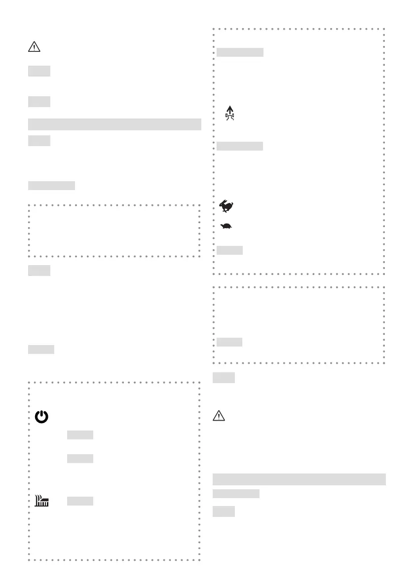
5.2.2 Power button
1.
Machine start-up. By pressing the button
(Fig.10.A) the LED (Fig.10.B) switches on and
the machine is ready for use.
NOTE The machine can be switched on
only if the operator presence lever and the
drive lever are released.
NOTE In case the machine is not oper-
ated, the LED switches o after 15 seconds
and the above-mentioned operation must be
carried out again.
2.
Cutting means engagement.
NOTE The cutting means engagement is
possible only by pressing the operator pres-
ence lever on the handle (see par. 6.3).
3.
Cutting means disengagement. With the
presence lever (Fig.10.A); the cutting means
stops whilst keeping the machine powered on.
5.2.3 Drive ON lever
IMPORTANT The engine has to be always started
with the drive disengaged.
This engages the wheel drive and allows the machine to
move forward.
It is located behind the handle.
Drive engaged. The lawn mower is driven
forward with the lever pulled against the
The lawn mower stops
moving forward when the lever is released.
IMPORTANT Avoid moving the machine backwards
when the drive is ON.
with the selection knob located on the right side of the
handle (Fig.10.C).
1. Maximum speed (about 5 Km/h).
2. Minimum speed
NOTE The last speed level selected remains set even
after the machine is switched o.
5.2.4 “ECO” button
The “ECO” mode allows to save energy when cutting
(Fig.10.D) to enable or disable the "Eco" mode.
This mode is automatically deactivated when the opera-
tor presence levers are released.
NOTE_It is not recommended to use the "ECO" func-
tion in heavy grass cutting conditions (cutting of dense,
high, humid grass).
5.3 CUTTING HEIGHT ADJUSTMENT
heights.
Carry out this operation when the cutting means is
stationary.
The cutting height is adjusted by using the designated
lever (Fig.11.A) that lifts or lowers the chassis to the desired
position.
6. USING THE MACHINE
IMPORTANT For instructions regarding the batteries,
refer to the specic manual.
6.1 PRELIMINARY PROCEDURES
Make sure that the safety key is not inserted in its slot. Place
the machine in a stable horizontal position on the ground.