- 6 -
To remove the OnCell 3120-LTE-1 from the DIN rail, pull down the
lever at the bottom of the DIN-rail kit.
Wall Mounting (optional)
For some applications, it may be more convenient to mount the OnCell
3120-LTE-1 to a wall, as illustrated below:
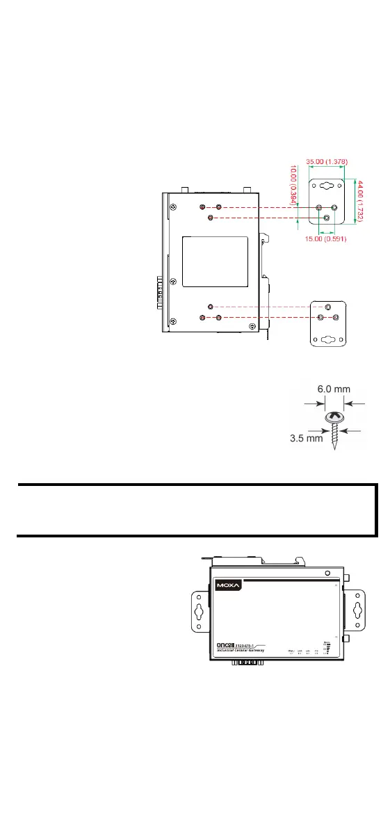
STEP 1:
Remove the aluminum
DIN
-
rail attachment plate
from the OnCell
3120-
-1, and then attach
-mounting plates
with M3 screws, as shown
in the adjacent diagram.
STEP 2:
Mounting the OnCell
3120-LTE-1 to a wall requires 4
OnCell 3120-LTE-1 device, with wall
mount plates attached as a guide, to mark the
correct locations of the 4 screws. The heads of the
screws should be less than 6.0 mm in diameter, and
the
shafts should be less than 3.5 mm in diameter,
as shown in the figure at the right.
Test the screw head and shank size by inserting the screws into
one of the k
eyhole shaped apertures of the wall-mounting
plates before attaching the plates to the wall.
STEP 3:
Once the screws are fixed into
the wall, insert
the four screw
heads through the large opening
of the keyhole
-shaped apertures
, and then
3120-LTE-1
downwards. Tighten the four
screws for added stability.
 Loading...