- 9 -
Wiring the Power Input
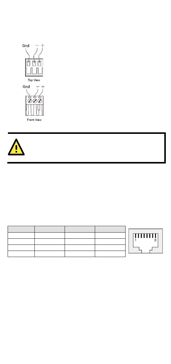
Top and front views of the terminal block connector are shown below:
STEP 1: Insert the negative/positive DC wires
into the
V-/V+ terminals, and the ground wire
ND terminal.
To keep the DC wires from pulling
-blade screwdriver to
-clamp screws on the front of
the terminal block connector.
Insert the plastic terminal block
connector prongs into the terminal block
receptor, which is
located on the bottom panel
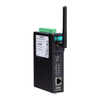
OnCell 3120-LTE-1.
OnCell 3120-LTE-1 to the DC power
inputs, make sure that the DC power source voltage is stable.
Communication Connections
10/100Base-T(X) Ethernet Port Connection
The 10/100Base-T(X) ports located on the front panel of the OnCell
3120-LTE-1 are used to connect to Ethernet-enabled devices.
Pinouts for both MDI (NIC-type) ports and MDI-X (HUB/Switch-type)
ports are shown below:
Serial DB9 Connection
The OnCell 3120-LTE-1 has one DB9 male port that supports RS-232,
RS-485-4W, RS-485-2W, and RS-422. The pin assignments are shown
in the table below: