Page 4 of 24 FLOMAX 8 BZ AL (en)
STORAGE PRECAUTIONS
Do not store filled with fluid at or below freezing temp of
process uid.
INSTALLATION
INSTALLATION FOR FLOMAX SELF PRIMING PUMPS
:
For optimum performance, place pump as close to liquid
source as possible to reduce suction lift to a minimum. For
best results, pump should be installed not more than 15 feet
above the liquid supply. Set the unit on solid footing and as
nearly level as possible.
Pipe or hose of the same size as anges provided should be
used. Reinforced rubber suction hose is recommended be-
cause it provides greater flexibility and prevents collapsing
due to vacuum in the suction line when pump is in operation.
Suction line should be as short as possible and have as few el-
bows or bends as possible to keep friction loss at a minimum.
Use pipe dope on all connections and make certain that all
ttings are tight, particularly on the suction line where an air
leak can prevent priming or reduce pump capacity.
A good suction strainer should be used. Suction strainers are
available from your MP Distributor. Refer to the accessory
section of the GENERAL PUMP PRICE LIST for the correct part
number
INSTALLATION FOR FLOMAX PUMPAKS:
Be sure that the pump housing is filled with liquid before
starting the pump. THE MECHANICAL SEAL IN THE PUMP
MUST NOT BE OPERATED DRY.
Pipe or hose of the same size (or larger) as inlet and outlet
openings should be used on the installation. When using
pipe, avoid sharp bends and use long radius elbows wherev-
er possible. This will keep friction loss at a minimum and al-
low the pump to operate more eectively. Use pipe dope on
all connections and be sure all ttings are airtight, especially
on the suction side of the pump. An air leak on the suction
side of the pump will prevent proper operation. A section of
non-collapsible hose between piping and pump may be used
as a vibration dampener.
BEARING INSTALLATION (PEDESTAL MODELS):
Check the shaft to insure that it rotates freely. Shafts should
be aligned in accordance with the instructions of the cou-
pling manufacturer. Final alignment must be performed after
the pump has been completely installed and the pump and
driver are at operating temperature. Proper shaft alignment is
the responsibility of the installer.
Piping should include shuto valves on both the discharge
and suction to isolate the pump for maintenance. Provisions
for suction and discharge pressure gages are recommended
for trouble shooting. The suction line should be as short as
possible, at least as large as the pump suction connection,
include as few ttings as possible and those should be long
radius to keep friction losses at a minimum.
Both suction and discharge piping should be supported in-
dependently of the pump. Never use excessive force to move
the pipe into place. This may impose a strain that will result
in misalignment between the pump and driver or otherwise
adversely aect the operation of the pump. After connecting
pipe to the pump rotate the shaft several times to check for
rubbing or binding.
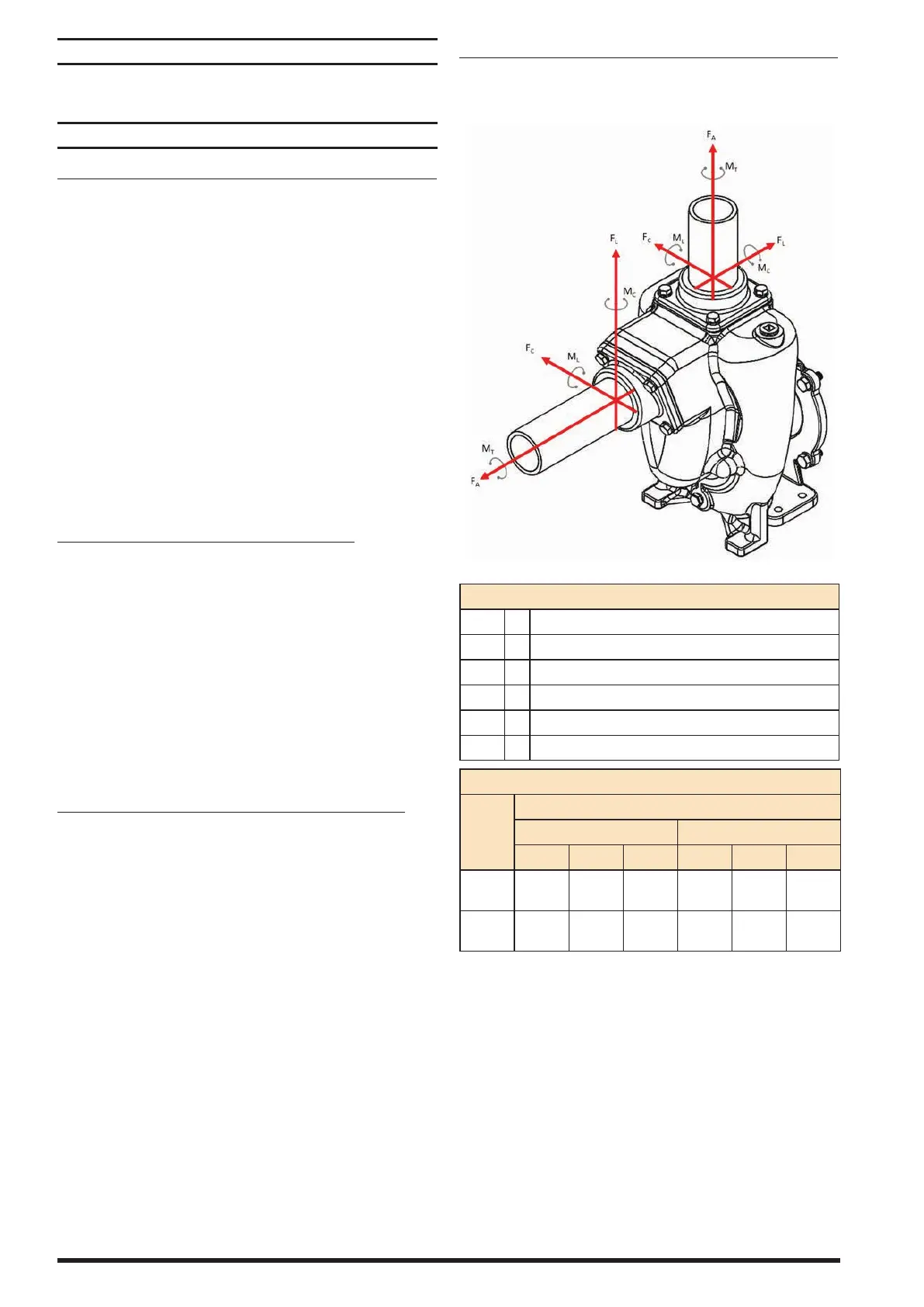
NSTALLATION FOR FLOMAX SELF PRIMING PUMPS
The permitted forces and moments on pump inlet
and outlet.
LEGENDS
F
L
- Longitudinal shear force
F
C
- Circumferential shear force
F
A
- Axial tension or compression force
M
L
- Longitudinal bending force
M
C
- Circumferential bending force
M
T
- Torsional moment
ALLOWABLE NOZZLE LOADS
Nozzle
Size
(in)
Small Flomax Flanges
Force lbs (N) Moment ft*lbs (N*m)
FL FC FA ML MC MT
1.5”
405
(1800)
405
(1800)
303
(1350)
100
(135)
149
(203)
129
(176)
2”
540
(2400)
540
(2400)
405
(1800)
177
(240)
266
(360)
230
(312)
 Loading...