FLOMAX 8 BZ AL (en) Page 5 of 24
MOTOR MOUNTING
Check rotation of the driver to be sure it coincides with the
required rotation of the pump. When viewed from the driver
end the rotation of the pump is CLOCKWISE.
A Pumpak shaft sleeve is machined to precisely t the shaft
of your driver. No provision is made for drive key and none is
required.
Loosen the drive clamp fasteners but do not remove. NOTE:
If the driver shaft is keyed, remove the key before attempting
to install the Pumpak. Slide the Pumpak assembly onto the
driver shaft, aligning the Cap Screw holes in the adaptor with
the tapped holes in the driver mounting face until the adap-
tor contacts the mounting face.
Install fasteners and tighten to secure Pumpak assembly to
the driver. First center then tighten the drive clamp assembly
to lock the shaft sleeve onto the driver shaft.
After all fasteners are tight including the drive clamp assem-
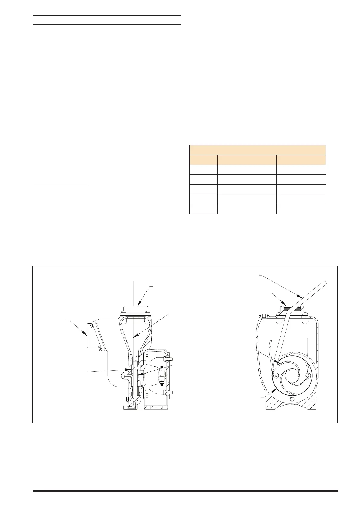
bly, remove the Assembly shim from the suction connection.
The shim was in place to establish clearance between the
face of the impeller and pump housing. Rotate the driver
slowly by hand to make certain that there is no rubbing.
Mounting Pumpak
Loosen impeller clamp nuts.
Do not use drive shaft key. Remove key if installed on drive
shaft.
Slide PUMPAK assembly onto the drive shaft. WARNING! If
PUMPAK does not slide freely STOP DO NOT HAMMER or
force PUMPAK. Be sure impeller clamp is loose. PUMPAK as-
semblies should slide on with hand pressure. Check for and
remove any burrs from drive shaft or bore of sleeve. Align
holes in adapter with holes in driver mounting face and slide
PUMPAK until adaptor contacts mounting face.
Attach Cap Screws and lockwashers and tighten to secure
PUMPAK assembly to driver. Tighten impeller clamp nuts to
lock impeller onto drive shaft.
TO ADJUST IMPELLER CLEARANCE:
NOTE: A shipping spacer was inserted at the factory for the
purpose of establishing the proper clearance between the
face of impeller and the wear plate.
1. Remove strip stock spacer only after tightening the
impeller.
2. Clearance between the impeller and wear plate is now
set to approximately 0.020”.
3. Turn over slowly to make certain pump rotates freely.
4. Loosen impeller clamp to adjust clearance between im-
peller and wear plate using a feeler.
5. Gauge in place of spacer. After clearance has been estab-
lished, tighten impeller clamp to lock impeller to shaft.
Torque Specications
Size Stainless Steel (ft-lbs) Steel GR5 (ft-lbs)
5/16” - 18” 10 - 14 14 - 20
3/8” - 16” 20 - 2 6 26 - 32
1/2” - 1 3” 34 - 42 70 - 80
1/2” - 20” 40 - 4 8 N/A
5/8” - 11” 75 - 85 N/A
(24 GAUGE)
DISCHARGE
IMPELLER
WEAR PLATE
DISCHARGE
WEAR PLATE
IMPELLER
SHIM
(24 GAUGE)
Figure 2
 Loading...