FLOMAX 8 BZ AL (en) Page 7 of 24
SEAL REPLACEMENT INSTRUCTIONS
DISASSEMBLE THE PUMP:
Drain the system of liquid, break suction and discharge pipe
unions, and, if necessary, remove all piping from the suction
and discharge openings. Remove the fasteners holding the
pump adaptor to the driver, loosen the drive clamp assembly,
and remove the PUMPAK.
To disassemble, remove the washers and hexnuts holding the
motor adaptor to the housing. Remove the housing. The im-
peller, drive sleeve, seal bellows, and the spring assembly will
now slide forward Free of the pump adapter.
The seal seat and seat cup will remain in the pump adaptor.
If not damaged or worn, do not remove. If necessary, remove
from the adaptor counter bore with a piece of wood or a
screwdriver handle inserted through the adaptor from the
drive end. A sharp tap or two is usually sucient to knock out
the seal seat. Use caution in removing the seal seat so as not
to crack a ceramic seat.
REMOVE IMPELLER
Remove seal bellows and spring assembly. On some models,
spring keeper can also be removed now before removing im-
peller.
NOTE: The seal bellows will be bonded to the shaft sleeve
and will require some patience and caution in removal in or-
der not to damage the seal bellow and cage.
MP Pumps rebuild kits include a new drive sleeve to avoid the
possibility of damaging the drive sleeve. See back of manual
for list of seal kits and corresponding rebuild kits. Impellers
are also available if wear or damage is present.
Remove locknut from shaft; unscrew the impeller from the
shaft sleeve counter-clockwise from the impeller end.
INSPECTION:
Check all parts for wear. For ease of reassembly shaft sleeve
should have all nicks and burrs removed. Clean with light cro-
cus cloth. Replace damaged parts with new parts.
Inspect the seal seat and washer, seat cup, and seal bellows
for grooves, cuts, scumarks, or other deterioration. If any of
the parts are damaged, a complete new assembly should be
installed.
6
54
3
1
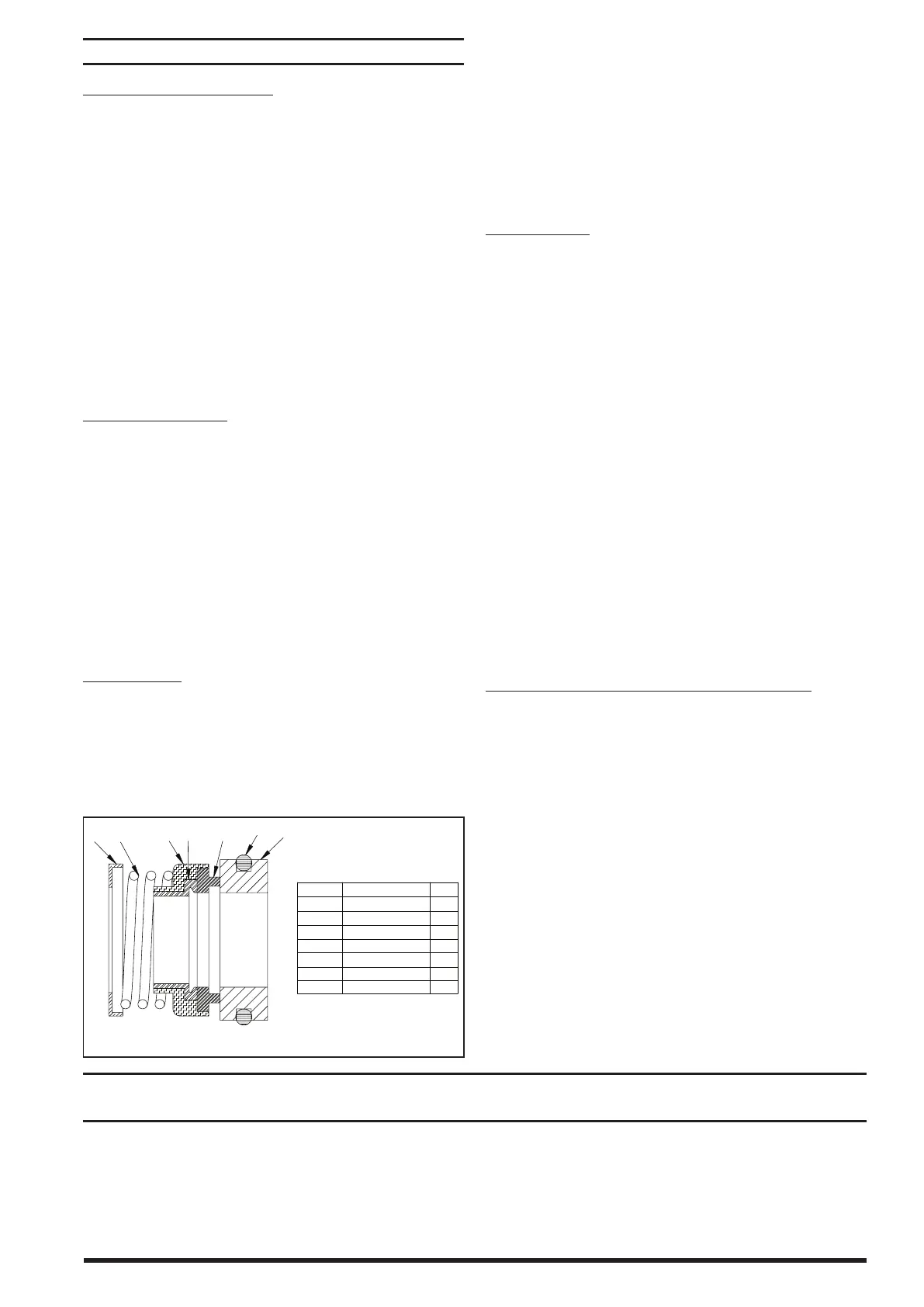
ITEM NO. DESCRIPTIONQTY.
Mating Ring
2
3
4
5
6
7
1
1
1
1
1
1
1
1
O-ring
Primary Ring
Elastomer Bellows
Drive Band
Spring
Spring Holder
inspect the lapped sealing face of carbon washer (Part 3) for
wear which would necessitate replacement.
Inspect lapped sealing face of oating seat (Part 4) in adapter
housing counterbore for scung or cracks. If necessary to re-
place, press out old seat and ring, and proceed as outlined in
paragraph on MOUNTING ADAPTER.
If spring and/or bellows (Part 1 and 2) are damaged and re-
quire replacement, lubricate the impeller sleeve with a clean
light oil and slide parts o sleeve.
REASSEMBLY:
All dirt and foreign matter should be removed. Recommend
only using new seals and elastomers when reassembling a
pump.
Lubricate seal seat cup with liquid soap (P-80 emulsifier) or
clean grease and press seal seat into adaptor counter bore,
seating it firmly and squarely. Use caution so as not to mar
the lapped face of the seal seat.
Assemble shaft sleeve; seal spring keeper, impeller and im-
peller nut. Before installing seal bellows and spring assembly,
lubricate the shaft sleeve and rubber bellows with liquid soap
(P-80 emulsier) or clean grease and press bellows and spring
assembly onto the shaft sleeve. The spring should engage the
spring keeper at the impeller end of the shaft sleeve.
To be properly positioned the washer must be rmly against
the rubber bellows member and the driving lugs of the wash-
er properly engaged. The raised shoulder on the seal wash-
er should be facing away from the impeller to contact the
lapped surface of the seal seat in the adaptor.
Slide impeller and seal assembly into the adaptor. Install drive
clamp assembly on the shaft sleeve but do not tighten.
Make sure the shim is installed between the impeller and the
wear plate. Do not remove the shim material before the drive
sleeve clamp has been tightened to the motor drive shaft.
INSTRUCTIONS FOR SET SCREW TYPE SEAL:
Do not remove the seal retaining clips. Slide the seal into
place on the shaft. The end of the shaft will be recessed
approximately 0.080” ± 0.020” from the end of the seal. The
proper seal working height is achieved when the seal faces
are set ush with the seal clips in place.
With the seal clips still in place tighten the seal fasteners with
a ball end allen wrench. It is important that the allen wrench
not rest upon the seal housing during tightening as this may
aect the position of the seal on the shaft. After the seal fas-
teners have been tightened the seal clips should be removed
and saved.
Do not use the seal shim with setscrew type seal.
For bellows seal install the seal spacer on the backside of the
impeller. Use a light grease or similar tacky material. Thread
impeller onto shaft. Install jam nut. Place O-ring onto seal
plate. Install impeller/bearing housing assembly into pump
housing. Install lock washers and hex nuts. Rotate the shaft
several times to check for rubbing or binding.
BEARING REPLACEMENT INSTRUCTIONS
(PEDESTAL MODELS)
The pump utilizes a single self-adjusting type mechanical seal
that is lubricated and cooled by the liquid in the pump.
THE PUMP MUST NEVER BE OPERATED WITHOUT LIQUID
IN THE HOUSING.
Check rotation of the driver to be sure it coincides with the
required rotation of the pump. When viewed from the driver
end the rotation of the pump is CLOCKWISE.
The pump’s grease lubricated bearings are sealed. They have
been pre-lubricated at the factory and require no further
lubrication or maintenance for the life of the bearing.
 Loading...