FLOMAX 8 BZ AL (en) Page 9 of 24
Lubricate the inside of the washer and bellows assembly (Part
2 and 3) with a clean light oil and slide it onto the impeller
drive sleeve only until it clears the chamfer.
Slide the seal bellows and washer assembly onto the impeller
drive sleeve. Push the seal down over the drive sleeve with
even pressure. Pull the seal head back up to the position
where there is no spring load. This insures proper assembly
on the drive sleeve.
Before sliding the impeller onto the drive shaft, wipe the
lapped sealing faces of the oating seat (Part 4) in the adapt-
er counterbore and the carbon washer (Part 3) on the bellows
assembly perfectly clean. Then lubricate both faces with a
clean light oil.
NOTE: The assembly of impeller and seal to the drive shaft
should take place as soon as the bellows assembly is slipped
on the impeller sleeve so as to avoid bonding of the bellows
to the sleeve at improper working height.
CAUTION: Foreign matter between sealing faces will cause
leakage and shorten the life of the seal.
MOUNTING GREASE LUBRICATED SEAL ASSEMBLY
Apply P80 to seal seat bore in seal housing and around O-ring
on carbon seal seat. Then press seal seat, by hand, into seal
seat bore making sure marked side of seal seat is down. Clean
and inspect for cracks, chips and deformities.
Dot
O Ring
Figure 5
Place gasket over studs and O-ring into groove then install
seal housing over studs with seal facing up with ¼ NPT holes
at 2 o’clock and 7 o’clock position. Inspect and wipe clean if
needed. Apply P80 to impeller drive sleeve and to interior
of seal bellows, and push onto drive sleeve with seal pusher
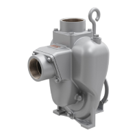
with silicon carbide seal facing downward towards impeller.
The silicon carbide face is a matte light gray. The carbon face
is a very dark gray/black. See the picture below. Some seals
have the same primary seal face and therefor the direction
does not matter.
Seal Face (black)
Seal Face (gray)
To
Impeller
Figure 6
Install seal spring over drive sleeve onto backside of silicon
carbide seal. Apply P80 to interior seal bellows of carbon seal
and push over drive sleeve with seal pusher carbon face up.
Inspect and wipe clean, if necessary. Install gasket over studs
onto seal housing. Apply P80 to seal seat bore of adapter and
around O-ring on seal seat. Push seal seat, by hand, into seal
bore – clean and inspect.
Install O-ring into adaptor groove. Apply P80 to O-ring. Place
adapter onto seal housing gasket, handle hole up, and attach
using 6 hex nuts and lock washers. Assemble clamp assembly
over drive sleeve. Leave loose.
Apply Gasoila onto threads of grease fitting and install to
lower pipe tting hole at 10 o’clock position in seal housing
and tighten by hand. NOTE: Do not get sealant into grease
fitting. Apply Gasoila to 1/8” NPT plug and install into pipe
tting at 5 o’clock position. Apply Gasoila to pressure release
valve threads and install into upper pipe tting hole at the 10
o’clock position.
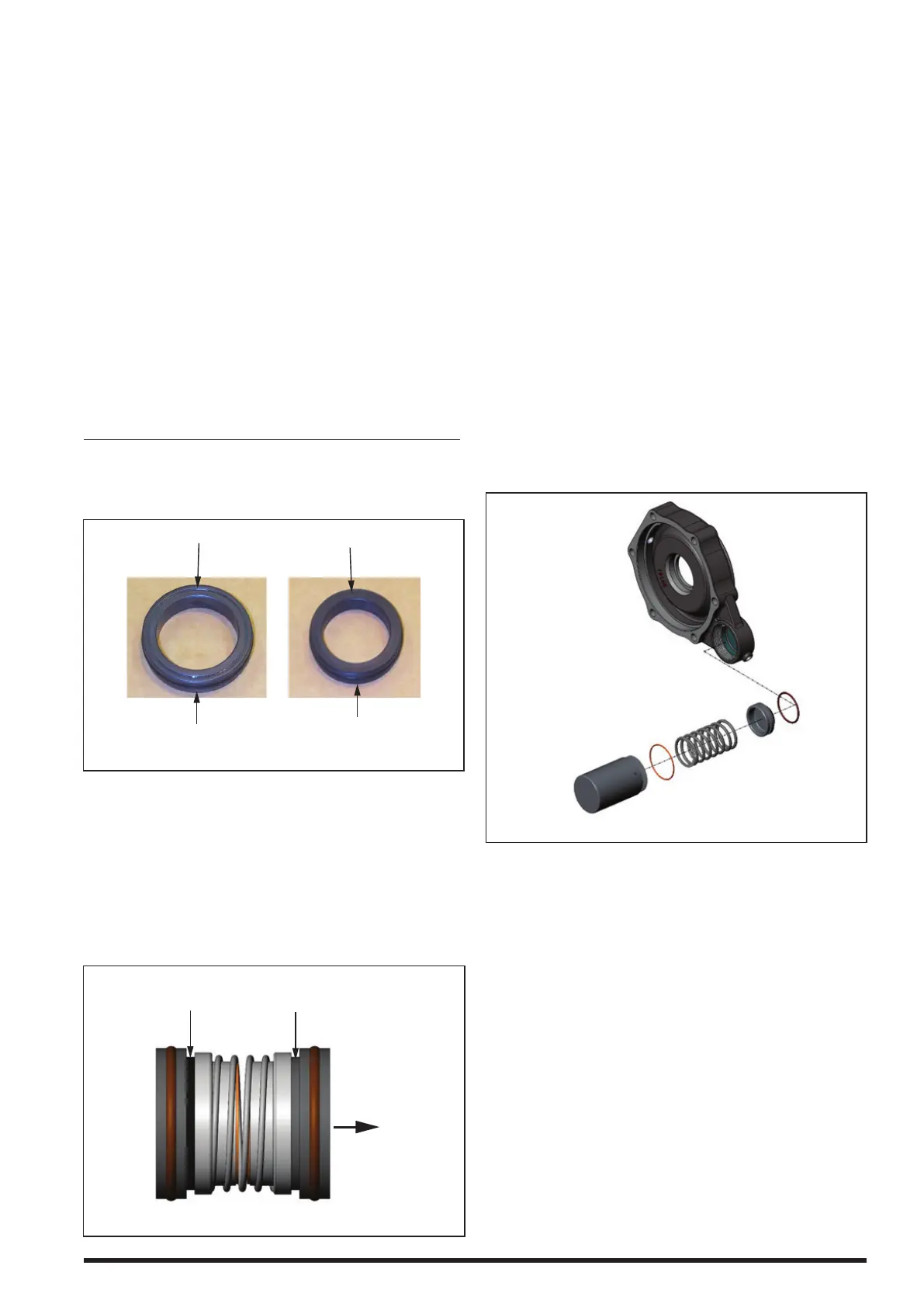
Fill seal cavity with grease until it comes out of the reservoir
hole. Assembly grease reservoir into adaptor as shown below.
Place smaller O-ring over the piston. Place the large O-ring
over the reservoir cover. Install the piston into the adaptor
hole. Place the spring within the piston. Thread the cover
into the adaptor.
Figure 7
Continue filling seal cavity until high-pressure grease reser-
voir is full. NOTE: When grease reservoir is full it will spit out
of the pressure release valve.
 Loading...